Difference between revisions of "User talk:DanielFilippi"
Jump to navigation
Jump to search
| Line 103: | Line 103: | ||
</imagemap> | </imagemap> | ||
==For Enhanced Swales== | |||
<imagemap> | |||
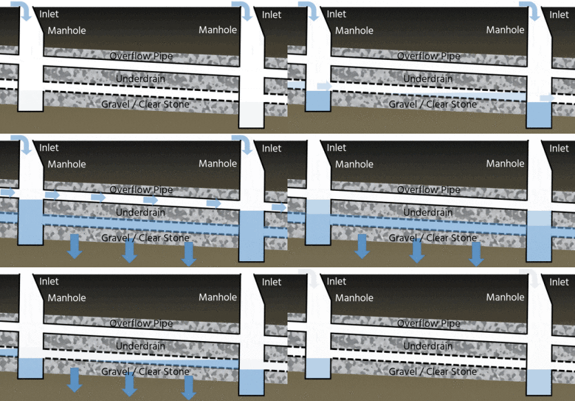
Image:Exfiltration Trench labeled.gif|417 × 194 pixels| | |||
rect 43 6 100 31 [[Inlets| Inlet]] | |||
rect 366 7 416 37 [[Inlets| Inlet]] | |||
rect 59 33 131 57 [[Exfiltration: Gallery| Manhole]] | |||
rect 273 26 350 61 [[Exfiltration: Gallery| Manhole]] | |||
poly 64 74 155 71 266 77 344 78 344 106 62 94 [[Overflow| Overflow Pipe]] | |||
poly 65 114 162 121 166 105 201 107 234 107 245 123 340 131 342 143 200 135 66 131 [[Underdrains| Underdrain]] | |||
rect 142 140 277 161 [[Reservoir aggregate| Gravel / Clear Stone]] | |||
</imagemap> | |||
==References== | ==References== | ||
Revision as of 20:04, 14 September 2021
For Infiltration Trench[edit]

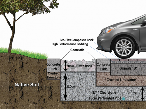
This infiltration trench features an inlet composed of filter fabric and decorative river stone, which provides some pretreatment and can easily be removed and replaced as part of routine sediment removal maintenance. For more details click here.
For Downspout disconnection[edit]

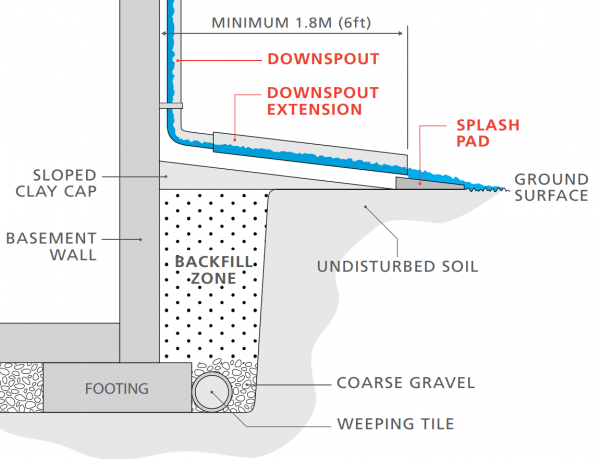
This schematic shows proper downspout disconnection of a building's downspout system with associated setback distances and items (weeping tile pipes, gravel, splash pad, etc. For more details click here.[1]
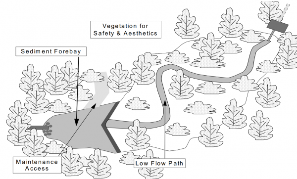
For Dry pond[edit]
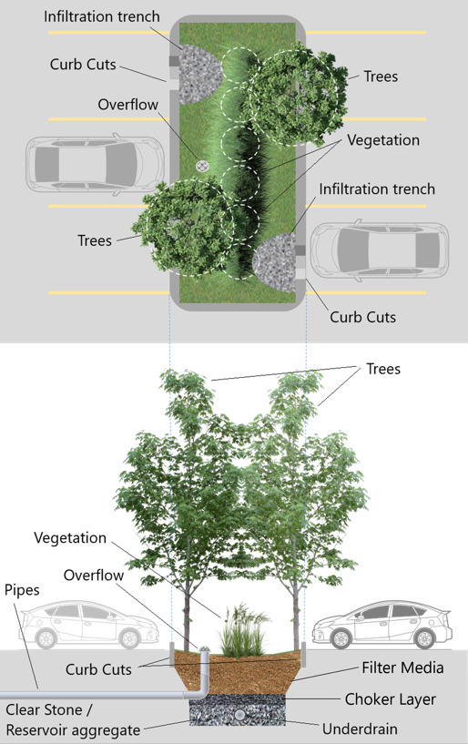
For Bioretention[edit]
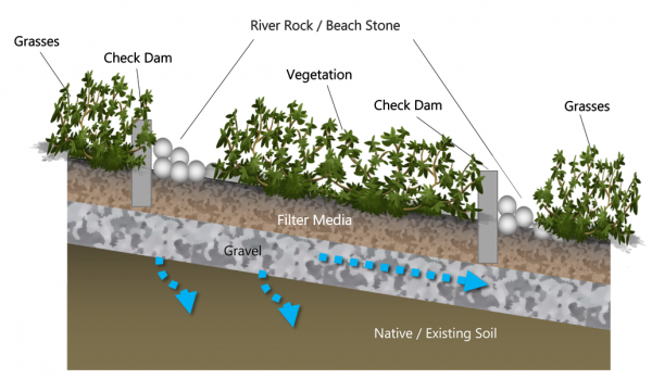
For Bioswales[edit]
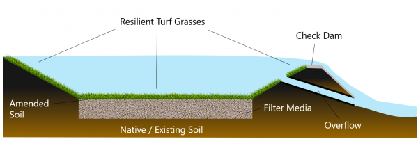
For Enhanced Swales[edit]
For Enhanced Swales[edit]
References[edit]
- ↑ The Institute For Catastrophic Loss Reduction. Protect your home from Basement flooding: Designed for safer living®. https://www.iclr.org/wp-content/uploads/PDFS/protect-your-home-from-basement-flooding.pdf. 2011. Accessed 3 September, 2021
- ↑ Ministry of the Environment. Stormwater Management Planning and Design Manual. https://dr6j45jk9xcmk.cloudfront.net/documents/1757/195-stormwater-planning-and-design-en.pdf. 2003. Accessed 3 September, 2021
