Difference between revisions of "Overflow: Installation"
Jump to navigation
Jump to search
JamesCowan (talk | contribs) |
JamesCowan (talk | contribs) |
||
| Line 19: | Line 19: | ||
<gallery mode="packed" widths=300px heights=300px> | <gallery mode="packed" widths=300px heights=300px> | ||
overflow-pipe-install.jpg | Overflow pipe installed to underdrain T-connection. | overflow-pipe-install.jpg | Overflow pipe installed to an underdrain T-connection. | ||
overflow-plastic-cap.jpg | Overflow installed with a plastic cap. Note that the use of plastic grates is discouraged. | overflow-plastic-cap.jpg | Overflow installed with a plastic cap. Note that the use of plastic grates is discouraged. | ||
</gallery> | </gallery> | ||
Revision as of 19:47, 19 July 2022
Overflows are features of inline facilities and convey larger storm events out of the LID feature.
Construction Steps:
- Connect the overflow drain to the underdrain
- Install overflow pit to grade at the location specified in the contract documents
- Fit a metal, domed grate to the overflow
Key Inspection Points:
- Overflow drain matches design specifications
- Overflow pit is positioned at the maximum water surface elevation of the practice, as per the contract documents
- Sufficient freeboard is provided between the overflow and inlet such that the inlet is not inundated by design storm flows
- Overflow grate matches design specifications
- Overflow grates located in high-traffic areas are screwed on or equipped with locks
Mistakes to Avoid:
- Backflows – ensure that backflows are avoided by confirming that inlet and overflow elevations match design specifications with surveys
- Incorrect sequencing – install overflow drain prior to backfilling with granular material and engineered soil
- Incorrect grate material – avoid using plastic overflow grates due to breakages and UV degradation
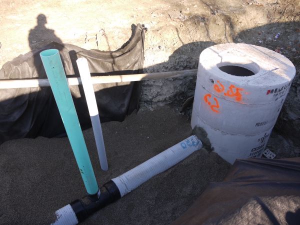
Overflow pipe installed to an underdrain T-connection.
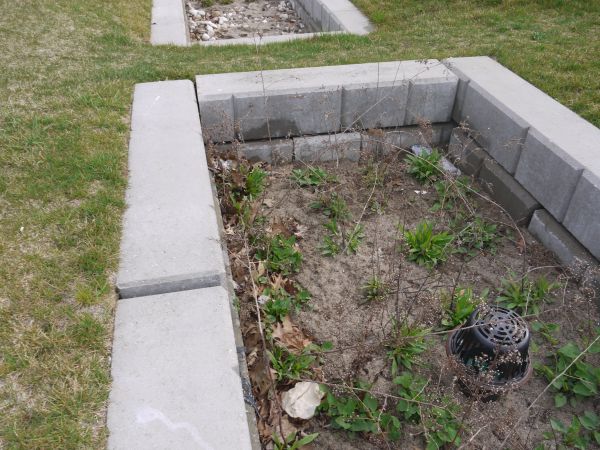
Overflow installed with a plastic cap. Note that the use of plastic grates is discouraged.

