Difference between revisions of "Inspection and Maintenance: Green Roofs"
(Created page with "thumb|750px|link=https://sustainabletechnologies.ca/app/uploads/2018/02/Green-Roofs-Fact-Sheet.pdf|Inspection & Maintenance Guidance of [[Green roofs best management practices. These specialized roofs are specially engineered and designed to support the growth of vegetation while protecting the structural integrity of the roof, aiding in helping to cool the building and effectively infiltrate, absorb and retain precipitation (TRCA, 201...") |
(No difference)
|
Revision as of 12:21, 8 August 2022

Overview[edit]
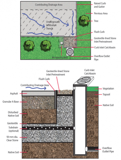
Underground infiltration systems is a general term that refers to best management practices (BMPs) that capture and temporarily store stormwater from hard surfaces. These systems treat stormwater by detaining it to allow suspended sediments to settle out and soaking it into the ground where it is filtered and cleansed by interaction with soil. Runoff water is delivered to the practice through pipes connected to catchbasins, hydrodynamic (i.e., oil and grit) separators, filters, manholes, sub-drains of other features or roof downspouts. They are installed below the local maximum frost penetration depth to ensure they continue to drain year-round. Water that is in excess of the storage capacity overflows to an adjacent drainage system (e.g., municipal storm sewer or other BMP), typically via pipe or manhole containing a control structure (e.g., weir wall), to safely convey flows during flood events. Depending on the permeability of the underlying soil, such practices may be designed without a sub-drain for full infiltration or with a sub-drain for partial infiltration. The sub-drain pipe may feature a flow restrictor (e.g., orifice cap, valve) for gradually releasing detained water and optimizing the amount drained by infiltration.

Key components of Underground Infiltration Systems to pay close attention to are the:
Trash, debris and sediment builds up at these locations and can prevent water from flowing into or out of the practice.
Associated Practices[edit]
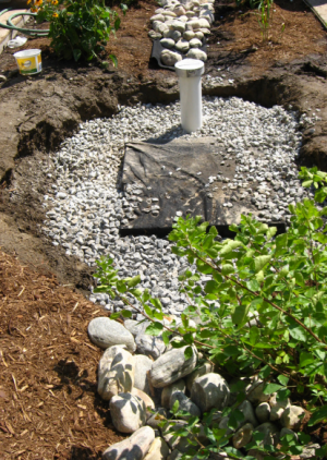
- Soakaways: Typically service individual lots and receive only roof and walkway runoff but can also be designed to receive overflows from other BMPs (e.g., rain barrels or cisterns, rain gardens, green roofs. Also known as infiltration galleries, French drains, dry wells or soakaway pits.
- Infiltration trenches: Linear oriented soakaways designed to fit into narrow strips of land between structures or properties, or along road rights-of-way; can also receive road runoff with adequate pretreatment devices upstream of inlets.
- Infiltration chambers: Include a range of proprietary modular structures installed underground that create large void spaces for temporary storage of stormwater while providing sufficient load bearing capacity to allow construction of structures on top of them. Applications are similar to infiltration trenches. Also known as infiltration tanks or vaults.
- Perforated pipe storm sewer systems or Exfiltration trenches: Linear-oriented infiltration trenches installed parallel with conventional storm sewer pipes and catchbasins that receive stormwater from them. May include manholes with perforated risers. Also known as exfiltration storm sewer, percolation drainage, or clean water collector systems.
Inspection and Testing Framework[edit]
Component |
Indicators |
Construction Inspection |
Assumption Inspection |
Routine Operation Inspection |
Verification Inspection |
|---|---|---|---|---|---|
| Contributing Drainage Area | |||||
| CDA condition | x | x | x | x | |
| Inlet | |||||
| Inlet/Flow Spreader Structural Integrity | x | x | x | ||
| Inlet/Flow Spreader Structural Integrity | x | x | x | x | |
| Perimeter | |||||
| BMP dimensions | x | x | x | ||
| Filter Bed | |||||
| Filter bed sediment accumulation | x | x | x | ||
| Underdrain & Monitoring Well | |||||
| Monitoring well condition | x | x | x | x | |
| Sub-drain/Perforated pipe obstruction | x | x | |||
| Outlets | |||||
| Overflow outlet obstruction | x | x | x | x | |
| Control Structure | |||||
| Control structure condition | x | x | x | x | |
| Control structure sediment accumulation | x | x | x | x |

Component |
Indicators |
Construction Inspection |
Assumption Inspection |
Routine Operation Inspection |
Verification Inspection | |
|---|---|---|---|---|---|---|
| Testing Indicators | ||||||
| Sediment accumulation testing | x | x | x | x | ||
| Natural or simulated storm event testing | x | (x) | ||||
| Continuous monitoring | x | (x) | ||||
| Note: (x) denotes indicators to be used for Performance Verification inspections only (i.e., not for Maintenance Verification inspections) | ||||||
- ↑ 1.0 1.1 1.2 TRCA. 2018. Fact Sheet - Inspection and Maintenance of Stormwater Best Management Practices: Green Roofs. https://sustainabletechnologies.ca/app/uploads/2018/02/Green-Roofs-Fact-Sheet.pdf
