Difference between revisions of "Planters: Sizing"
Jump to navigation
Jump to search
Jenny Hill (talk | contribs) m |
Jenny Hill (talk | contribs) m |
||
| Line 28: | Line 28: | ||
| 0.3 | | 0.3 | ||
|- | |- | ||
| Pipe diameter reservoir | | Pipe diameter reservoir | ||
| Is equal to underdrain pipe diameter | | Is equal to underdrain pipe diameter | ||
Revision as of 17:56, 19 March 2018
This article is specific to Flow-through stormwater planters, vegetated systems that do not infiltrate water to the native soil.
If you are designing a planted system which does infiltrate water, see advice on Bioretention: Sizing.
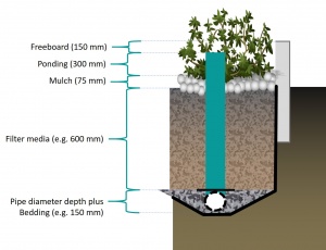
The dimensions of a stormwater planter are largely predetermined according to the function of the component. As they do not contain a storage reservoir the planters rely more upon careful selection of materials. Both the filter media and the perforations of the pipe play critical roles for flow control.
| Component | Recommended depth (with underdrain pipe) | Typical void ratio (VR) |
|---|---|---|
| Ponding (dp) | ≥ 300 mm | 1 |
| Mulch | 75 ± 25 mm |
|
| filter media (dm) |
|
0.3 |
| Pipe diameter reservoir | Is equal to underdrain pipe diameter | 0.4 |
| Pipe bedding (db) | 50 mm (although commonly omitted altogether). | 0.4 |
Calculate the maximum overall depth[edit]
- Step 1: Determine what the planting needs are and assign appropriate depth of media, using the table above.
- Step 2: Select an underdrain pipe diameter (typically 100 - 200 mm), assign this as an 'embedding' depth.
- Step 3: Calculate the maximum possible storage reservoir depth beneath the pipe (ds):
Where:
- f' = Design infiltration rate in mm/hr, and
- 38.4 comes from multiplying desired drainage time of 96 hours by void ratio of 0.4
Additional step for system without underdrain[edit]
- Step 4: Determine maximum permissible ponding depth (dp):
Where:
- f' = Design infiltration rate in mm/hr, and
- 19.2 comes from multiplying desired drainage time of 48 hours by void ratio of 0.4. Note that conceptually the drainage of the ponded area is limited by ex-filtration at the base of the practice.
- Step 5: Sum total depth of bioretention, and compare to available space above water table and bedrock. Adjust if necessary.
Calculate the remaining dimensions[edit]
- Step 6: Multiply the depth of each separate component by the void ratio and then sum the total to find the 1 dimensional storage (in mm).
- Step 7: Calculate the required total storage (m3):
Where:
- RVCT is the Runoff volume control target (mm),
- Ac is the catchment area (Ha),
- C is the runoff coefficient of the catchment area, and
- 0.1 is the units correction between m3 and mm.Ha.
- Step 8. Divide required storage (m3) by the 1 dimensional storage (in m) to find the required footprint area (Ap) for the bioretention in m2.
- Step 9. Calculate the peak flow rate (Qp, in L/s) through the filter media:


