Difference between revisions of "Flow through riser"
Jump to navigation
Jump to search
Jenny Hill (talk | contribs) m |
|||
| (4 intermediate revisions by one other user not shown) | |||
| Line 1: | Line 1: | ||
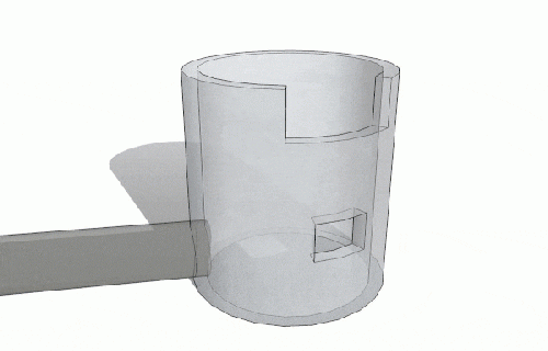
[[File:Riser.gif|thumb|A two stage riser with low flow controlled with an orifice and high flow controlled with a weir.]] | [[File:Riser.gif|thumb|500px|A two stage riser with low flow controlled with an orifice and high flow controlled with a weir.]] | ||
There are many configurations for multistage risers according to the flow control requirements. | |||
It is easiest to begin downstream and design with the the highest return period required in mind. | |||
e.g. start by specifying the pipe/culvert component to control the 100 year flow. | |||
Then to work backwards to size the lip or weir at the top of the structure to meet the next return period flow. | |||
The riser is then designed with flow through one or more orifices. | |||
<math> | <math> | ||
| Line 7: | Line 14: | ||
C_{w}L_{w}\left ( Z-Z_{0} \right )^{1.5}, & Z_{0}\leq Z\leq Z_{0}+H_{0}\\ | C_{w}L_{w}\left ( Z-Z_{0} \right )^{1.5}, & Z_{0}\leq Z\leq Z_{0}+H_{0}\\ | ||
C_{d}A_{0}\sqrt{2g\left (Z-Z_{0}-0.5H_{0}\right)}, & Z_{0}+H_{0}\leq Z\leq Z_{1}\\ | C_{d}A_{0}\sqrt{2g\left (Z-Z_{0}-0.5H_{0}\right)}, & Z_{0}+H_{0}\leq Z\leq Z_{1}\\ | ||
C_{w}L_{w}\left ( Z-Z_{1} \right )^{1.5}+C_{d}A_{ | C_{w}L_{w}\left ( Z-Z_{1} \right )^{1.5}+C_{d}A_{o}\sqrt{2g\left (Z-Z_{1}\right)}, & Z_{1}<Z | ||
\end{matrix}\right. | \end{matrix}\right. | ||
</math> | </math> | ||
{{Plainlist|1=Where: | |||
*''Z'' = the depth of ponded water in m, | |||
*''Z<sub>0</sub>'' = the elevation of the bottom of the orifice in m, | |||
*''H<sub>0</sub>'' = the height of the orifice in m, | |||
*''Z<sub>1</sub>'' = the elevation of the weir in m, | |||
*''C<sub>w</sub>'' = the weir coefficient, | |||
*''L<sub>w</sub>'' = the length of the weir in m, | |||
*''C<sub>d</sub>'' = the discharge coefficient of the orifice (often defaulted to 0.6 for a sharp edged orifice), | |||
*''A<sub>o</sub>'' = the cross-sectional area of the orifice in m<sup>2</sup>, | |||
*}} | |||
==See also== | |||
*[[Detention basins]] | |||
*[[Flow control]] | |||
==For review== | |||
https://www.hydrologystudio.com/no-fail-detention-pond-design/ | |||
Latest revision as of 14:43, 17 December 2021
There are many configurations for multistage risers according to the flow control requirements. It is easiest to begin downstream and design with the the highest return period required in mind. e.g. start by specifying the pipe/culvert component to control the 100 year flow. Then to work backwards to size the lip or weir at the top of the structure to meet the next return period flow.
The riser is then designed with flow through one or more orifices.
Where:
- Z = the depth of ponded water in m,
- Z0 = the elevation of the bottom of the orifice in m,
- H0 = the height of the orifice in m,
- Z1 = the elevation of the weir in m,
- Cw = the weir coefficient,
- Lw = the length of the weir in m,
- Cd = the discharge coefficient of the orifice (often defaulted to 0.6 for a sharp edged orifice),
- Ao = the cross-sectional area of the orifice in m2,
See also
For review
https://www.hydrologystudio.com/no-fail-detention-pond-design/

