Difference between revisions of "Bioretention: Partial infiltration"
Jump to navigation
Jump to search

| Line 1: | Line 1: | ||
<imagemap> | <imagemap> | ||
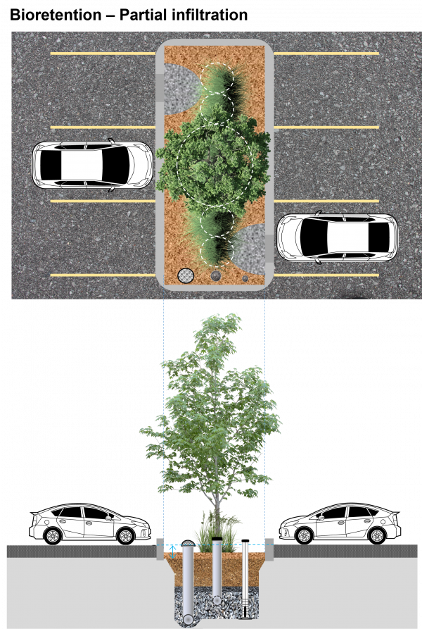
File:Bioretention | File:Bioretention partial infiltration res agg..png|thumb|600px|Bioretention cell schematic depicting partial infiltration capturing and treating runoff from the surrounding parking lot, while also allowing excess water to leave the site via perforated underdrain and overflow pipes. For more standardized details click here for the [https://www.toronto.ca/wp-content/uploads/2021/09/965f-ecs-specs-gi-design-criteria-manual-Sep2021.pdf Design Criteria for Green Infrastructure in the Right-of-Way document] <span style="color:red">''A note: The following is an "image map", feel free to explore the image with your cursor and click on highlighted labels that appear to take you to corresponding pages on the Wiki.''</span> | ||
poly 869 241 867 322 947 334 1020 367 1051 373 1085 334 1153 318 1389 377 1387 247 [[Mulch|Mulch]] | poly 869 241 867 322 947 334 1020 367 1051 373 1085 334 1153 318 1389 377 1387 247 [[Mulch|Mulch]] | ||
Revision as of 21:00, 16 February 2022

Bioretention cell schematic depicting partial infiltration capturing and treating runoff from the surrounding parking lot, while also allowing excess water to leave the site via perforated underdrain and overflow pipes. For more standardized details click here for the Design Criteria for Green Infrastructure in the Right-of-Way document A note: The following is an "image map", feel free to explore the image with your cursor and click on highlighted labels that appear to take you to corresponding pages on the Wiki.
Overview[edit]
Over soils with slow infiltration rates, it is advantageous to drain a portion of the stored water prior to any upcoming storm. This popular design choice can optimize annual water balance, mitigate peak flow rates and by ensuring water flow through, can reduce the accumulation of sodium and chlorine ions from winter salting.
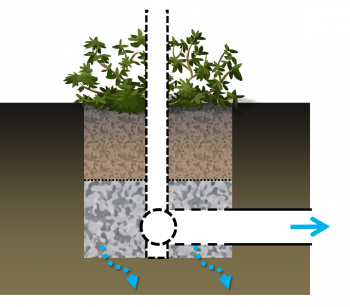
Partially infiltrating bioretention with underdrain.
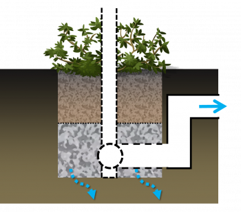
Partially infiltrating bioretention with anaerobic/aerobic storage zone.
Materials[edit]
Research[edit]
Bioretention: Partial infiltration volume

