Difference between revisions of "Overflow"
Jump to navigation
Jump to search
Jenny Hill (talk | contribs) m |
Jenny Hill (talk | contribs) m |
||
| Line 1: | Line 1: | ||
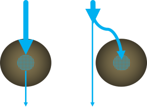
[[File:Routing.png|thumb|Conceptual diagram of the excess routing alternatives: On the left, excess flow leaves the cell via an overflow; on the right, excess flow is diverted so that only the design volume enters the cell.]] | [[File:Routing.png|thumb|Conceptual diagram of the excess routing alternatives: On the left, excess flow leaves the cell via an overflow; on the right, excess flow is diverted so that only the design volume enters the cell.]] | ||
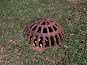
[[File:BeehiveGrate.jpeg|thumb|Domed, metal overflow/outlet grate<br> Photo credit:Aaron Volkening]] | [[File:BeehiveGrate.jpeg|thumb|Domed, metal overflow/outlet grate<br>[[Acknowledgements| Photo credit: Aaron Volkening]]]] | ||
==Routing== | ==Routing== | ||
Revision as of 19:09, 2 November 2017
Routing[edit]
- Infiltration facilities can be designed to be inline or offline from the drainage system.
- Inline facilities accept all of the flow from a drainage area and convey larger event flows through an overflow outlet. The overflow must be sized to safely convey larger storm events out of the facility.
- The invert of the overflow should be placed at the maximum water surface elevation of the bioretention area, (typically 150 - 250 mm above the surface).
- Offline facilities use flow splitters or bypass channels that only allow the required water quality storage volume to enter the facility.
- Higher flows are diverted and do not enter the infiltration practice. A pipe can by used for this, but a weir or curb cut minimizes clogging and reduces the maintenance frequency.
Options[edit]
| Feature | Anti Vandalism/Robust | Lower Cost Option | Self cleaning |
|---|---|---|---|
| Dome grate | x | ||
| Flat grate | x | ||
| Plastic grate | x | ||
| Metal grate | x | ||
| Catch basin | x | ||
| Ditch inlet catch basin | x | x | |
| Curb cut | x | x | x |

