Inspection and Maintenance: Underground Infiltration Systems
Overview[edit]
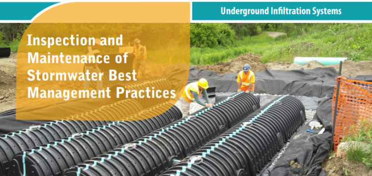
Underground infiltration systems is a general term that refers to best management practices (BMPs) that capture and temporarily store stormwater from hard surfaces. These systems treat stormwater by detaining it to allow suspended sediments to settle out and soaking it into the ground where it is filtered and cleansed by interaction with soil. Runoff water is delivered to the practice through pipes connected to catchbasins, hydrodynamic (i.e., oil and grit) separators, filters, manholes, sub-drains of other features or roof downspouts. They are installed below the local maximum frost penetration depth to ensure they continue to drain year-round. Water that is in excess of the storage capacity overflows to an adjacent drainage system (e.g., municipal storm sewer or other BMP), typically via pipe or manhole containing a control structure (e.g., weir wall), to safely convey flows during flood events. Depending on the permeability of the underlying soil, such practices may be designed without a sub-drain for full infiltration or with a sub-drain for partial infiltration. The sub-drain pipe may feature a flow restrictor (e.g., orifice cap, valve) for gradually releasing detained water and optimizing the amount drained by infiltration.
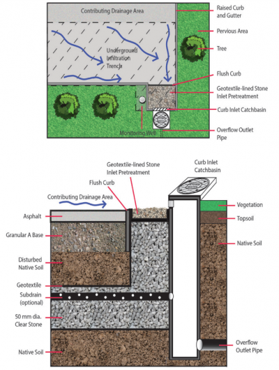
Key components of Underground Infiltration Systems to pay close attention to are the:
Trash, debris and sediment builds up at these locations and can prevent water from flowing into or out of the practice.
Associated Practices[edit]
- Soakaways: Typically service individual lots and receive only roof and walkway runoff but can also be designed to receive overflows from other BMPs (e.g., rain barrels or cisterns, rain gardens, green roofs. Also known as infiltration galleries, French drains, dry wells or soakaway pits.
- Infiltration trenches: Linear oriented soakaways designed to fit into narrow strips of land between structures or properties, or along road rights-of-way; can also receive road runoff with adequate pretreatment devices upstream of inlets.
- Infiltration chambers: Include a range of proprietary modular structures installed underground that create large void spaces for temporary storage of stormwater while providing sufficient load bearing capacity to allow construction of structures on top of them. Applications are similar to infiltration trenches. Also known as infiltration tanks or vaults.
- Perforated pipe storm sewer systems or Exfiltration trenches: Linear-oriented infiltration trenches installed parallel with conventional storm sewer pipes and catchbasins that receive stormwater from them. May include manholes with perforated risers. Also known as exfiltration storm sewer, percolation drainage, or clean water collector systems.
Inspection and Testing Framework[edit]
Component |
Indicators |
Construction Inspection |
Assumption Inspection |
Routine Operation Inspection |
Verification Inspection |
|---|---|---|---|---|---|
| Contributing Drainage Area | |||||
| CDA condition | x | x | x | x | |
| Inlet | |||||
| Inlet/Flow Spreader Structural Integrity | x | x | x | ||
| Inlet/Flow Spreader Structural Integrity | x | x | x | x | |
| Perimeter | |||||
| BMP dimensions | x | x | x | ||
| Filter Bed | |||||
| Filter bed sediment accumulation | x | x | x | ||
| Underdrain & Monitoring Well | |||||
| Monitoring well condition | x | x | x | x | |
| Sub-drain/Perforated pipe obstruction | x | x | |||
| Outlets | |||||
| Overflow outlet obstruction | x | x | x | x | |
| Control Structure | |||||
| Control structure condition | x | x | x | x | |
| Control structure sediment accumulation | x | x | x | x |
Component |
Indicators |
Construction Inspection |
Assumption Inspection |
Routine Operation Inspection |
Verification Inspection | |
|---|---|---|---|---|---|---|
| Testing Indicators | ||||||
| Sediment accumulation testing | x | x | x | x | ||
| Natural or simulated storm event testing | x | (x) | ||||
| Continuous monitoring | x | (x) | ||||
| Note: (x) denotes indicators to be used for Performance Verification inspections only (i.e., not for Maintenance Verification inspections) | ||||||
Construction Inspection Tasks[edit]
Construction inspections take place during several points in the construction sequence, specific to the type of LID BMP, but at a minimum should be done weekly and include the following:
- During site preparation, prior to BMP excavation and grading to ensure the CDA is stabilized and/or flow diversion devices are in place and confirm that construction materials meet design specifications
- At completion of excavation and grading, prior to backfilling and installation of pipes to ensure depths, slopes and elevations are acceptable
- At completion of installation of geotextile/pipes, prior to completion of backfilling to ensure slopes and elevations are acceptable
- After final grading, prior to surface course installation to ensure depths, slopes and elevations are acceptable
- Prior to hand-off points in the construction sequence when the contractor responsible for the work changes (i.e., hand-offs between the storm sewer servicing, paving, building and landscaping contractors)
- After every large storm event (e.g., 15 mm rainfall depth or greater) to ensure ESCs and pretreatment or flow diversion devices are functioning and adequately maintained. View the table below, which describes critical points during the construction sequence when inspections should be performed prior to proceeding further. You can also download and print the table here
Construction Sequence Step & Timing |
Inspection Item |
Observations* |
|---|---|---|
| Site Preparation - after site clearing and grading, prior to BMP excavation and grading, prior to BMP excavation and grading | Natural heritage system and tree protection areas remain fenced off | |
| ESCs protecting BMP layout area are installed properly | ||
| CDA is stabilized or runoff is diverted around BMP layout area | ||
| BMP layout area has been cleared and is staked/delineated | ||
| Benchmark elevation(s) are established nearby | ||
| Construction materials have been confirmed to meet design specifications | ||
| BMP Excavation and Grading - prior to backfilling and installation of geotextile/pipes | Excavated soil is stockpiled outside the CDA | |
| Excavation location, footprint, depth and slope are acceptable | ||
| Compaction of subsoil where load-bearing portions of the system will be installed is acceptable | ||
| Excavation bottom and sides roughened to reduce smearing and compaction | ||
| BMP Installation – after installation of geotextile/ pipes/structures, prior to completion of backfilling | Installation of structural components (e.g., control manhole, maintenance hatches) is acceptable | |
| Sub-drain trench dams installed correctly (location, elevation) | ||
| Installations of sub-drain pipes (e.g., locations, elevations, slopes) & maintenance access hatches are acceptable |
Routine Maintenance - Key Components and I&M Tasks[edit]
Regular inspections (twice annually, at a minimum) done as part of routine maintenance tasks over the operating phase of the BMP life cycle to determine if maintenance task frequencies are adequate and determine when rehabilitation or further investigations into BMP function are warranted.
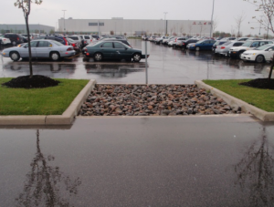
Table below describes routine maintenance tasks for underground infiltration systems (infiltration chambers, infiltration trenches, bioswales, etc.) organized by BMP component, along with recommended minimum frequencies. It also suggests higher frequencies for certain tasks that may be warranted for BMPs located in highly visible locations or those receiving flow from high traffic (vehicle or pedestrian) areas. Tasks involving removal of trash, debris and sediment and weeding/trimming of vegetation for BMPs in such contexts may need to be done more frequently (i.e., higher standards may be warranted).
| Component | Description | Inspection & Maintenance Tasks | (Pass) Photo Example | (Fail) Photo Example |
|---|---|---|---|---|
| Contributing Drainage Area (CDA) |
Area(s) from which runoff directed to the BMP originates; includes both impervious (i.e., roofs and pavements) and pervious (i.e., landscaped) areas. |
|
||
| Pretreatment |
Devices or features that retain trash, debris and sediment, oil and grease; help to prevent obstructions and clogging of the infiltration area. Examples are eavestrough screens, catch basin inserts (screens, baffles, filters) and sumps, oil and grit separators, geotextile-lined inlets, filters, isolator rows, and water quality forebay units. |
|
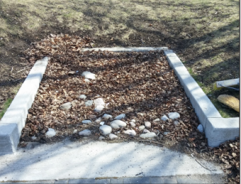
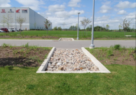 Geotextile-lined stone inlet is free of sediment, trash and debris. Stones to slow down and spread out inflowing water remain in place. |
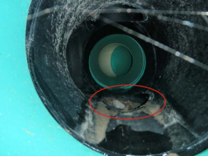
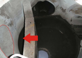
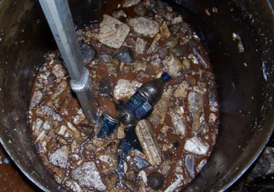
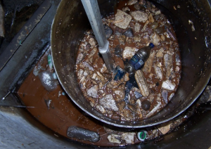 Accumulated sediment, trash and debris in the hydrodynamic (i.e., oil and grit) separator is occupying greater than 50% of its storage capacity. (Photo Source: SWC Canada, 2020)[2] |
| Inlets |
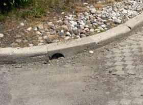
Structures that deliver water to the BMP such as curb-cuts and geotextile-lined inlets or pipes connected to catchbasins, hydrodynamic (oil and grit) separators (HDS), filters, manholes, sub-drains of other features or roof downspouts. |
|
||
| Overflow Outlet |
Structures (e.g., sub-drain/underdrain pipe connected to a manhole, conventional storm sewer pipe, or control manhole with weir wall) that convey flow exceeding the storage capacity to another drainage system or BMP. |
|
||
| Sub-drain |
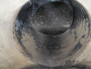
Comprised of perforated pipe(s) surrounded by gravel and may be wrapped in geotextile filter fabric; installed in the gravel water storage layer or chamber unit openings to collect and convey treated water to an adjacent drainage system or other BMP; may also include a flow restrictor. |
|
||
| Monitoring well |
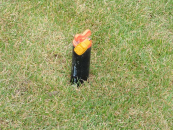
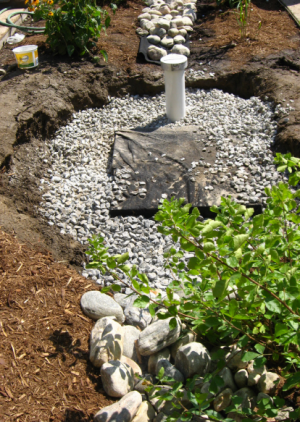
Perforated standpipe that extends from the bottom of the excavation to just below the pavement surface and contains perforations or slots to allow measurement of subsurface water level; used to track drainage performance over the operating life cycle of the BMP. |
|
Tips to Preserve Basic BMP Function[edit]
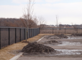
- Prohibit stockpiling of soil, sand, compost or unwashed gravel within the CDA and inlets to prevent clogging with sediment.
- For BMPs with sub-drains/underdrains and flow restrictors, pretreatment devices that prevent floating trash and debris from entering the practice should be used to prevent obstruction of the sub-drain pipe/flow restrictor.
- For BMPs equipped with pretreatment that detains floating contaminants (e.g., oil and grease, trash and debris), such as hydrodynamic separators/oil and grit separators or forebays with baffle walls, remove trash and debris first using a bucket strainer. Floating oils and grease should then be removed off the top of the water using a vacuum truck.
- Provide a means of draining infiltration chambers by gravity (e.g., pipe and valve through the control structure weir wall) to make inspection and maintenance work that requires drainage of the BMP (e.g., filter bed and control structure inspection and sediment removal, repairs to control structure) easier to perform.
- To remove accumulated sediment from underdrain pipes and chamber system units, a hydrovac truck equipped with a JetVac nozzle should be employed that uses pressured jets of water to propel itself through the structure while scouring and directing suspending sediments to a collection point. As the nozzle is retrieved, the sediment is flushed into the manhole or catchbasin sump for removal by vacuuming. Selecting an appropriate JetVac nozzle will depend on the structure being cleaned. For chamber system units, fixed nozzles designed for culverts or large diameter pipe cleaning with rear-facing jets are preferable (consult product manufacturer for further guidance).
- ↑ 1.0 1.1 1.2 1.3 TRCA. 2018. Fact Sheet - Inspection and Maintenance of Stormwater Best Management Practices: Underground Infiltration Systems. https://sustainabletechnologies.ca/app/uploads/2018/02/Underground-Infiltration-Systems-Fact-Sheet.pdf
- ↑ Storm Water Compliance (SWC) Canada Inc. 2020. OIL GRIT SEPARATORS/WATER QUALITY STRUCTURES. Accessed 02 August 2022. https://www.swccanada.com/system-types/oil-grit-separators
