Bioretention: Construction
This section is also applicable to:
Construction Tasks Table[edit]
| Construction Stage | Construction Task | Bioretention | Bioswale | Rain garden |
|---|---|---|---|---|
| Pre-Construction | Verification of Siting and LID Design | x | x | x |
| Communication and Utilities Coordination | x | x | x | |
| Installation of ESC and Construction Fencing | x | x | x | |
| ESC Inspection and Maintenance (ongoing) | x | x | x | |
| Excavation and Mass Grading |
Clearing and Grubbing | x | x | x |
| Excavation | x | x | x | |
| Rough Grade | x | x | x | |
| Verification of Grading/Survey* | x | x | x | |
| Scarification (if applicable) | x | x | x | |
| Backfill Granular, Utilities and Pipes |
Geotextile (if applicable) | x | x | x |
| Impermeable Liner (if applicable) | x | x | ||
| Underdrain (if applicable) | x | x | ||
| Overflow or Overflow Drain (if applicable) | x | x | x | |
| Monitoring Well (if applicable) | x | x | ||
| Clean Out Port | x | x | x | |
| Storage Reservoir | x | x | ||
| Stone Choker Layer (if applicable) | x | x | ||
| Curbing (if applicable) | x | x | ||
| Pre-treatment and Inlet | x | x | x | |
| Soil/Filter Media | x | x | x | |
| Finishing Grades: Inlet, Outlet, Biomedia and Plants |
Finishing Grading | x | x | x |
| Riprap/Large Stone (if applicable) | x | x | x | |
| Plant Verification and Installation | x | x | x | |
| Mulch Placement | x | x | x | |
| Stabilizing Contributing Drainage Area - Planting Adjacent Vegetation |
x | x | x | |
| As-built Survey | x | x | ||
| Permanent Fencing (if applicable) | x | x | ||
| Post-Construction | Identify and Address Deficiencies | x | x | x |
| Assumption/Certification Protocols | x | x | x |
Construction Tasks Described[edit]
Pre-Construction (KM)[edit]
When the design is 90% complete, the project manager (PM) should conduct a walk-through of the site to verify that the designs match site conditions. This site walk-through is a critical step in the transition from design to construction and helps the project manager plan for future pre-bid or pre-construction meetings. Think carefully about how a contractor will be able to build the LID practice. At this stage, determine if the design drawings and construction notes address specific LID construction requirements, and determine whether they contain inaccuracies or are missing detail. The table below identifies details key points and considerations for the walk-through.
| Verification point | Key considerations |
|---|---|
| Adjacent land uses |
|
| Contributing and receiving drainage areas |
|
| Seasonal maintenance operations | |
| Location of LID features |
|
| Existing and planned infrastructure/utilities |
|
| Property boundaries and building foundations |
|
| Natural heritage features and existing vegetation |
|
| Access, sequencing, staging, and constructability |
|
LID construction notes[edit]
LID design drawings need detailed construction notes within the design drawings. These notes should include:
- sequencing and staging areas
- material specifications
- testing requirements
- installation procedures
- elevations and invert details for inlet, outlet, and overflow features
- grading details for conveyance features
- erosion and sediment control requirements
- inspection and maintenance responsibilities during construction and prior to assumption
The last two bullets require further comment. LID facilities are most vulnerable to sedimentation and clogging during their own construction and construction of adjacent and connected lands. LID construction contracts should specify a sufficient combination of ESC measures and inspection and maintenance of the LID facility during the construction and assumption phases to ensure that it will function without remediation. Contracts for larger-scale projects, e.g., where the LID facility in question is part of a road reconstruction project or subdivision development, should contain clear terms covering responsibilities for keeping sediment from entering newly constructed LID features and removing it if necessary.
The project contract and tendered drawings, including details, notes, ESC requirements, material specifications, and testing requirements should align. Given that most standard contract templates do not include wording specific to LID construction, considerations for LID can be placed under special provisions within the contract.
Details within the drawings and contract should also be accurately reflected in the tender bid form. A detailed bid form that reflects the entirety of the work allows contractors to deliver accurate bids, lessens the likelihood of project shortcuts, and helps to ensure transparency amongst bids. Ultimately, clear bid pricing reduces the potential for misunderstandings and conflicts and attracts experienced contractors.
Minimum contractor requirements[edit]
Many contractors are unfamiliar with building LID practices, so project managers should consider minimum contractor requirements. Consider mandating contractor training, attendance at pre-bid meetings, LID project references, and bid bond insurance as prerequisites.
 
|
| A simple departure from the design—installing a T-junction (top) in place of a Y-junction (below) would have made it extremely difficult or impossible to inspect this underdrain and flush it out. (Image sources: CVC) |
After securing a contractor, a pre-construction meeting between the project manager, project engineer, and contractor will facilitate an efficient job site and reduce the potential for miscommunication. These meetings should cover:
- LID design details and construction notes
- material specifications, inspections, and chain-of-custody
- access routes and storage areas
- protection of LID practices: phasing, ESC, and perimeter fencing
- equipment requirements and recommendations
- verification of field changes
- plant establishment and warranty-period maintenance
- ownership and assumption protocols
- project inspection plan
- verification processes for field changes to the design and material substitutions
The table below expands upon the bullets above and provides helpful guidance on communication topics at the pre-construction meeting. Given the lead-up time needed for testing requirements of specified materials, these discussions should occur soon after the contract is awarded, ideally 2 months prior to project construction.
| Communication topic | Guidance |
|---|---|
| LID design details and construction notes |
|
| Material specifications, inspections, and chain-of-custody |
|
| Access routes and storage areas |
|
| Protection of LID practices during construction: phasing, ESC, and perimeter controls |
|
| Equipment requirements and recommendations |
|
| Verification of field changes |
|
| Plant establishment and warranty-period maintenance |
|
| Ownership and assumption protocols |
|
| Project inspection plan |
|
Inspection plan[edit]
The inspection and maintenance page gives detailed guidance on how to conduct construction inspections for LID practices. Generally, construction inspections should be continuous as the work progresses. If this isn’t possible, critical inspection points are:
- site preparation
- excavation
- installation of pipes, granular, and biomedia
- finishing grades
- surface treatment installation: pavers, plants, porous concrete, etc.
- after rain events (see ESC inspection and maintenance)
- whenever sub-contractors or utilities begin work (hand-off points)
The last element—inspection of sub-contractors—requires further comment. For example, if a sub-contractor is installing the curbing, they need to understand the purpose of the curbing and curb cuts, i.e., that they are meant to direct water into the LID facility, not to the closest catch basin. Without this knowledge, the sub-contractor may mistakenly build the curbs as they usually do: to direct water into a catchbasin.
Utilities coordination[edit]
Similarly, if the LID practice is in close proximity to sub-surface utilities, the utility owner may use their own contractors to perform related work. If this is the case, these sub-contractors must also be made aware of the LID practice’s purpose, how compaction affects performance, keeping the LID practice clear of excavated dirt and generally how their work could impede the construction and performance of the LID practice. In general, communication between the contractors, project managers, and project engineers should be frequent and open.
Erosion and sediment controls, construction limits, natural heritage protection, and perimeter controls
| Comnponent | Description | Inspection & Maintenance Tasks | (Pass) Photo Example | (Fail) Photo Example |
|---|---|---|---|---|
| Contributing Drainage Area (CDA) |
Area(s) from which runoff directed to the BMP originates; includes both impervious and pervious areas. |
|


ESC Inspection and Maintenance
Excavation and Mass Grading (KM)[edit]
Clearing and grubbing is the stripping of vegetation and topsoil prior to excavation and rough grading within designated areas.
Construction steps
- Clear trees, large shrubs, stumps, etc. (grubbing).
- Use appropriately sized machinery (e.g. a mini-excavator) to strip sod and ground-level vegetation (clearing).
- Stockpile materials within designated areas if necessary. If the materials are being hauled offsite, stripped materials ideally would go straight into the back of a dump truck.
- Secure stockpiles with appropriate erosion and sediment control (ESC) measures if the material must be stored before hauling offsite or will be reused.
Key inspection points
- Structural ESC measures are in place before clearing and grubbing begin.
- Natural heritage features, including trees, and construction limits are clearly marked and respected by the contractor.
- Contractor cleared and grubbed only within designated areas and according to the phasing plan.
Mistakes to avoid
- clearing more area than is needed
- insufficient marking of areas to be protected
- stockpiling materials without ESC controls or for extended periods of time
- leaving heavy equipment in the facility’s footprint
- making excessive passes with heavy equipment in the LID practice’s footprint without scouring soil afterward
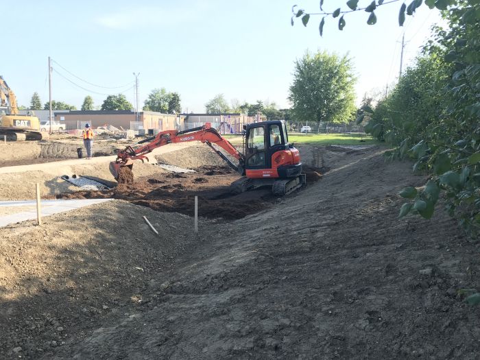
Excavation to the specified depths in the drawings is critical to the LID feature’s future performance. It also requires heavy machinery which, if used incorrectly, can compact soils and lower their native infiltration rates.

Construction steps
- Mark out the limit of excavation.
- Use predefined access routes to move heavy equipment.
- Cut and stabilize access and staging areas.
- Cut and stabilize channels and slopes.
- Excavate the LID feature from the outside-in whenever possible. A standard excavator (10-45 tons) has a longer reach than mini (<6 tons) or midi excavators (6-10 tons) and can be the best choice despite its weight, since it may not need to enter into the facility’s footprint to complete the job. However, a mini excavator would be the best choice if entry into the LID feature’s footprint is necessary.
- Excavate to within 100 mm of the final grade.
- Check grades with appropriate equipment (transit levels, etc.).
- Stockpile materials in a designated area if it must be stored before hauling.
Key inspection points:
- Confirm the limit of excavation.
- Use of excavation equipment specified in the contract, in the required manner (from the outside in, with a mini excavator, etc.).
- Confirm excavated rough grade and final grade prior to backfilling using survey equipment
- Use of toothed bucket and scouring the bottom of practice if applicable
- If appropriate, measure compaction using a cone penetration test or a cone penetrometer
- If appropriate, field verify infiltration rates at excavated bottom of practice using Guelph permeameter or double ring infiltrometer
Mistakes to avoid:
- making too many passes with heavy machinery within the LID footprint.
- leaving heavy machinery within the LID’s footprint (for breaks, lunch, overnight, etc.)
- using the wrong equipment
- over excavating
- smearing the bottom of the practice with the bucket, which can compact native soils
Fine grading and verification
Scarification and soil amendments
Backfill Granular and Pipes (JC)[edit]
Geotextile

Geotextiles are filter fabrics that can be installed to separate dissimilar soils and prevent the migration of materials. As such, proper installation of geotextiles is important for ensuring the proper division of materials.
Construction Steps:
- Roll out fabric on the flattened sub-grade surface
- Provide a minimum overlap of 300 mm between adjacent lengths of geotextile. If the manufacturer specifies a greater overlap, follow the manufacturer’s specification
- Fabric should be secured in place with stakes along the edge of the sub-grade surface and where lengths of fabric overlap
- Provide 500 mm of excess at the ends of each length of fabric
- Excess material should be folded on top of the infiltration medium/choker course once installed
- Provide cuts for trees where appropriate
Key Inspection Points:
- Geotextile is clean and free of damage
- Geotextile delivered to the site matches the design specifications and is approved by the engineer prior to installation
- Sufficient overlap is provided between lengths of fabric
- Geotextiles have been applied as per the manufacturer’s guidelines
- Structural considerations for geotextiles have been made when applied adjacent to infrastructure and the geotextile can handle expected structural loads
- Class II geotextiles conform to OPSS 1860
Mistakes to Avoid:
- Wrinkles in the fabric – follow the manufacturer’s procedure for installation to ensure geotextiles lie smooth on sub-grade
- Unnecessary application of geotextile – mixing of media is negligible where structural loads are not expected, so geotextile does not need to be applied. Also geotextiles should not be used where root growth is encouraged to penetrate different layers of media
For more information on geotextiles, see the page on geotextiles.
Underdrains
Underdrains are pipes that can be included to collect subsurface water. Their design is determined by the drainage requirements of the feature.
Construction Steps:
- Install the underdrain to grade with a consistent slope of 0.5% to 1.0%
- Connect overflow risers with single-elbowed ‘y’ connections or 45° elbows
- Situate maintenance risers where siltation is expected in drain lines (such as at junctions or where grade and direction changes occur)
- Mark the locations of risers
- Use video inspections to confirm that the interior of the underdrain remains free of debris after construction
Key Inspection Points:
- Size, type, and material of the underdrain conforms to the design specifications
- Underdrain is perforated prior to arrival on-site
- Drain material is resistant to UV radiation and any chemicals in the soil and groundwater
- Clean-outs are positioned correctly and spaced appropriately for the size of the underdrain
- Any manual perforations are approved by the engineer
- Pipe grade matches design specifications
- Tie-in locations to municipal sewers meet City specifications
Mistakes to Avoid:
- Incorrect overflow risers – ensure single-elbowed ‘y’ connections or 45° elbows are used for overflow risers instead of ‘T’ connections
- Incorrect drain size – confirm underdrain has an internal diameter greater than or equal to 200 mm to reduce freezing and allow cleaning and camera inspections
- Potential for clogging – Remove sock from underdrain prior to installation
For more information on the design of under-drains, see the page on under-drains.
Impermeable Liners

Impermeable liners can be applied when LID features are not intended to infiltrate runoff into the underlying soil. Where building foundations that are adjacent to the LID feature are not waterproofed, liners can be used to protect neighbouring infrastructure.
Construction Steps:
- Compact 30 – 50 mm of sand over the soil onto which the membrane will be installed to protect against punctures. Alternatively, a geotextile can be used in the place of sand
- Place lengths of liner on the bed of the facility as per the manufacturer’s specifications
- Provide 150 mm of overlap between adjacent lengths of liner
- Secure liner in-place and bond together the overlapping portions of liner as specified by the manufacturer
- Where pipes provide drainage from the practice, a flange should be sealed to the pipe and liner.
- Compact sand or apply cushion fabric on top of the liner to protect against punctures
Key Inspection Points:
- Liner is confirmed to match design specifications
- Liner installation conforms to manufacturer’s specifications
- Minimum overlap between lengths of liner is achieved
- Need for impermeable liner is confirmed through field verification of setbacks to adjacent infrastructure
- Sand and/or geotextile are applied on both sides of the liner to protect against punctures
- Lengths of liner are bonded together to ensure protection against groundwater contamination
For more information on impermeable liners, see the page on liners.
Overflow or Overflow Drain
Overflows are features of inline facilities and convey larger storm events out of the LID feature.
Construction Steps:
- Connect the overflow drain to the under-drain
- Install overflow pit to grade at the location specified in the contract documents
- Fit a metal, domed grate to the overflow
Key Inspection Points:
- Overflow drain matches design specifications
- Overflow pit is positioned at the maximum water surface elevation of the practice, as per the contract documents
- Sufficient freeboard is provided between the overflow and inlet such that the inlet is not inundated by design storm flows
- Overflow grate matches design specifications
- Overflow grates that are located in high-traffic areas are screwed on or equipped with locks
Mistakes to Avoid:
- Backflows – ensure that backflows are avoided by confirming that inlet and overflow elevations match design specifications with surveys
- Incorrect sequencing – install overflow drain prior to backfilling with granular material and engineered soil
- Incorrect grate material – avoid using plastic overflow grates due to breakages and UV degradation
For more information on overflow drains, see the page on overflows.
Monitoring well
Monitoring wells are important for sampling procedures and ensuring that bioretention features are performing as intended.
Construction Steps:
- Anchor the perforated pipe to the bottom of the LID feature
- Install a lockable cap to the top of the standpipe to protect against vandalism
Key Inspection Points:
- Pipe is perforated, rigid, and matches design specifications
- Well is installed according to contract documents
- Geotextile sock is wrapped around the perforated portion of the well
Mistakes to Avoid:
- Incorrect sequencing – ensure that standpipe is installed prior to backfilling with granular material
For more information on monitoring wells, see the page on monitoring wells.
Backfill Granular and Pipes (SPC)[edit]
Storage Reservoir
INSERT YOUTUBE LINK: https://www.youtube.com/watch?v=Ng_s2ErvPqk&t=58s
The storage reservoir layer holds and directs the stormwater into the underlying/native soils. The LID facilities, if applicable, should be filled with uniformly graded, washed stone (20 mm – 50 mm) that provides 30 to 40% void space.
Construction steps:
- Backfill material from outside of the LID facility to avoid compaction and sediment entering the facilities. Use a slinger truck if possible.
- Place the material to the elevation and thickness as per the design specifications.
Key Inspection Points:
- Material arrival to the site:
- Check chain of custody
- Verify it meets specifications as per design
- Verify no debris or fines within the aggregate (it’s a washed stone)
- Granular material should be 19 - 50 mm clear stone or as per design. See Aggregates for further details.
- Installed aggregate is at the correct elevation as per design.
Mistakes to Avoid:
- Accepting material that does not meet design requirements and specifications.
- Installing material with heavy equipment from the inside of the LID facility
- Installing frozen aggregate. Do not install frozen aggregate
- Leaving heavy equipment (excavator) for long periods of time within the LID facility.
For more information on the storage reservoir, see the page: Reservoir aggregate.
Stone Choker Layer
INSERT VIDEO: K:\Watershed Management\Integrated Water Management Implementation\Fletchers Creek SNAP\Haggert Ave Road Retrofit\3 - Photos\Construction Overview Presentation\Video--> HaggertAve_Final.MP4
In LID facilities, a choker layer of ≥ 100 mm depth is recommended to prevent migration of finer filter media into the underlying storage reservoir aggregate. Similar to the storage reservoir material, this aggregate layer should be a washed 5 – 10 mm stone not containing any debris. Installation of aggregate choker layer should not be done when frozen.
Follow the construction guidance shown above in the section “Storage reservoir”
For more information on the choker layer, see the page: Choker layer
Curbing
"'INSERT VIDEO FROM HAGGERT AVE: \\Hqcvcfs01\cvc2\Watershed Management\Integrated Water Management Implementation\Fletchers Creek SNAP\Haggert Ave Road Retrofit\3 - Photos\Construction Photos\Site Visit_20201120\Riverstone Construction Haggert Ave Inlet_F.mp4
It is very important to make sure that the contractor responsible for curb construction understands curb cut designs and elevations. This is often a new technique for contractors, and they may not understand the overall concept of water in the gutter line being directed behind the gutter.
Construction Steps:
- Place the right forms (rolled curve vs standard) in the inlet location.
- Pour concrete.
- Shape the inlet
- Add the river stone on top of the fresh concrete (if applicable)
- Provide sufficient curing time, according to CSA standard A23.1-09.
Key Inspection Points:
- Use of proper curb form by sub-contractor.
- Curb type aligns with design.
- Curb cut location, type and dimension aligns with design.
- Designated concrete wash out is in place and away from LID facility.

Mistakes to Avoid:
- Elevated curb cuts and reverse slopes (sloping from back of curb towards instead of depressing from gutter line towards the back).
- Wrong curb cut width size.
- Use of wrong curb form.
- Concrete wash out within or upstream of LID facility.
- Lack of communication to concrete contractor or ready-mix driver explaining the function and importance of protecting the LID feature.
For more information on curb cuts, see these pages: Curb cuts, Curb cuts: Gallery and Bioretention: Streetscapes
Pre-treatment and Inlet
Pre-treatment structures are most cost effective when they slow down incoming flows, collect sediment for easy clean out, and slowly release water to the bioretention facility mitigating erosion. Pretreatment structures/strategies can include curb cuts, Aggregates, proprietary devices like filters or hydrodynamic separators, vegetation, concrete sumps, membrane filters, overland flow sumps, etc.
Construction Steps:
Installation of pre-treatment features will vary based upon type. Similarly, installation timeline will range with type and could occur at excavation and mass grading, curb work or at finishing grade. Given pre-treatment features are typically integrated with the LID inlet coordination amongst multiple sub-contractors is sometime needed. The following details steps for various pre-treatment types:
- Vegetation: Follow the guidance shown below in the section “Plant Material Verification and Installation”
- Curbing: Follow the guidance shown above in the section “Curbing”.
- Aggregate: Follow the guidance shown above in the section “Stone reservoir”.
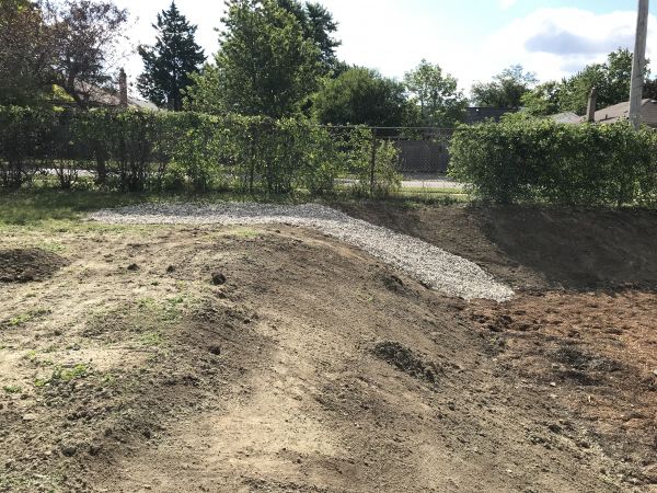
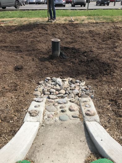
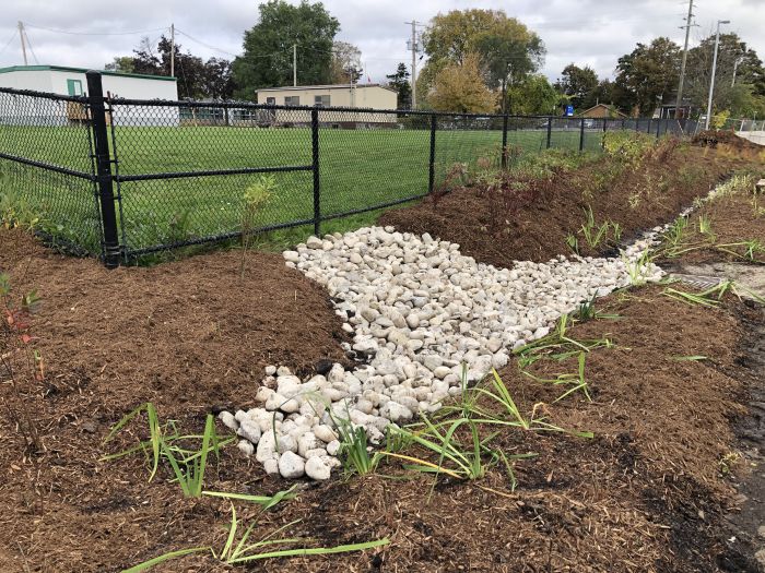
Aggregate material (rock) installed as the inlet and pre-treatment device in the rain garden at Glendale P.S. in Brampton, ON. The runoff comes from a vegetated swale into the inlet, conveying it into the rain garden.
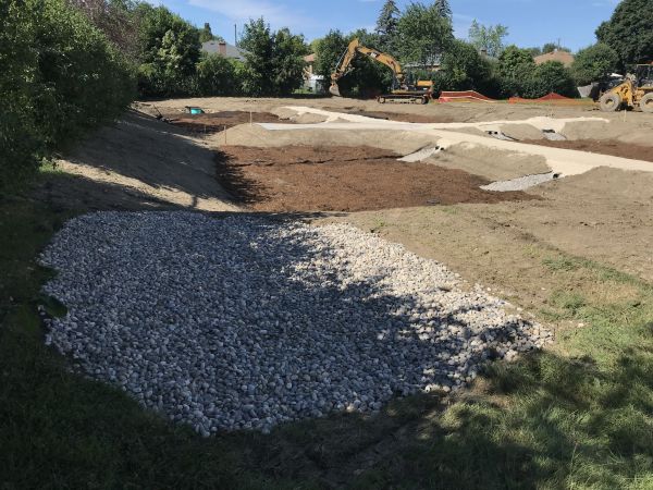
Aggregate material (rock) installed as the inlet and pre-treatment device in the rain garden at Glendale P.S. in Brampton, ON. The runoff comes from a vegetated swale into the inlet, conveying it into the rain garden.
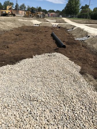
Aggregate material (rock) installed as the inlet and pre-treatment device in the rain garden at Glendale P.S. in Brampton, ON. The runoff comes from a vegetated swale into the inlet, conveying it into the rain garden.


- Proprietary pre-treatment device:
- Excavate and prepare base for proprietary pre-treatment device according to design.
- Install proprietary pre-treatment device according manufacturer directions.
- Manufacturer representative may need to confirm proper installation and functioning through approved testing and inspection.
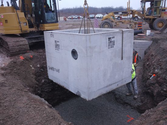
Installation of Jellyfish filter and sorbtive media vault at the IMAX bioswale project in Mississauga, ON.
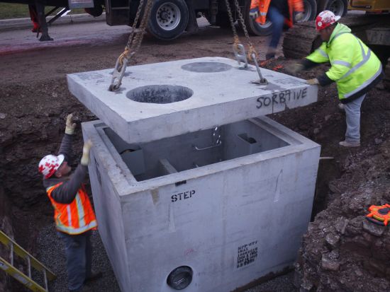
Installation of Jellyfish filter and sorbtive media vault at the IMAX bioswale project in Mississauga, ON.
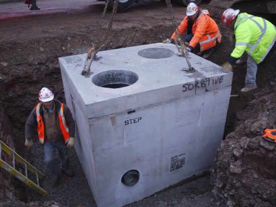
Installation of Jellyfish filter and sorbtive media vault at the IMAX bioswale project in Mississauga, ON.


Key Inspection Points:
- Verify that the correct pre-treatment device (jellyfish filter, vegetation, curbing, etc.) is being installed.
- Verify that all components of the pre-treatment device are installed
- Verify correct size and location of pre-treatment device.
- Verify correct elevation, slope, and footing according to design
- Is it tied into the curb, downspout, or other inlet? Or could happen before the curbing?
- Wet weather performance check:
- Does it work?
- Is water entering the LID facility properly?
- Is sediment and debris accumulating?
- Is it dissipating erosive forces?
Mistakes to Avoid:
- Pre-treatment component parts are missing
- Grading/elevation errors that deviates from design
- Incorrect pipe inverts causing short circuiting
- Insufficient grade drop or slope into pre-treatment to ensure positive flow of water
- Improper grading from pre-treatment to LID feature inhibiting positive flow
- Insufficient sump depth to account for sediment and debris accumulation
- Using wrong concrete forms if concrete curbs are part of pre-treatment.
For more information about pre-treatment strategies and their design, visit these page: Pretreatment and Pretreatment features.
Soil Media / Filter Media
Bioretention can be constructed over any soil type, but hydrologic soil group A and B are best for achieving water balance objectives. Facilities designed to infiltrate water should be located on portions of the site with the highest infiltration rates. STEP has detailed construction guidance on soil amendments available on its [Construction Specifications for Implementing Compost Amended Planting Soil in Ontario] webpage. These resources include specification details and a spreadsheet calculator for determining soil and amendment volumes.
Construction Steps:
- Apply soil media in 150-300 mm lifts until desired top elevation of bioretention, bioswale or rain garden area is achieved.
- Apply soil media with slinger trucks when possible. This type of equipment will reduce the need to move soil media manually or by backhoe.
- Thoroughly wet each lift before adding the next and wait until water has drained through the soil before adding the next lift.
- If amending soils:
- Stockpile native soils in designated areas.
- Mix selected additives with native soils using a plumbus.
- Sling soils into the LID feature whenever possible.
Key Inspection Points:
- When material arrives to the site: perform chain of custody, visual inspection and ribbon test to ensure that material meets design requirements.
- Soil/filter media’s design parameters and assumptions should be confirmed through in-situ permeability testing (e.g., permeameter measurements to determine hydraulic conductivity). Results of permeability testing should be reviewed by the designer and, if required, changes to the LID design may be needed. See Testing for more information regarding testing procedures.
- Ensure that soil media is being applied to the correct depth.
- Ensure that the native soil and amended material are well blended.
- Measure potentially compacted soils using a cone penetration test or a cone penetrometer.
Mistakes to Avoid:
- Machine compaction - equipment should not be operated within the infiltration practice.
- Soil material: Accepting material that does not meet design specifications and requirements.
- Application: Applying the next lift without letting dry the previous lift of filter material.
Finishing Grades: Inlet, Outlet, Biomedia, Plants (SPC)[edit]
Finish Grading
The finish grading process is another critical handoff moment as a number of elements such as curbs, sidewalks, soils and vegetation start to come together to create the functional and aesthetic value of a site. The same supervision and communication that was put into controlling ESC in earlier stages is also required during finish grading. In many cases, more attention to detail is needed for elements in this phase that will create or not the success of the final product.
Construction steps Soil Media:
- Backfill or sling material from outside of the LID facility at the lowest possible speed to avoid loss of component material.
- Apply material in 150-300 mm lifts until the desired elevation and thickness, allowing for positive flow.
- Wet material between lifts, allowing for drying before backfilling/slinging another lift.
Key Inspection Points:
Mistakes to avoid:
Large Stone and Riprap
Riprap serves as a protective layer to: prevent sediment entering the underlying layers and clogging the LID facility, dissipate stormwater energy, and stabilize the terrain and slope.
Construction Steps:
- Backfill the material from the outside of the LID facility to avoid compaction.
- Ensure the material is being placed to the elevation and thickness to the design requirements.
Key Inspection Points:
- Arrival of material to the site: material meets specifications as per design, no debris in the aggregate and, if possible, washed or clean stone with little to no fine materials in it.
- Placement: material is backfilled to the right depth and elevation.
Common Mistakes to Avoid:
- Use of wrong material that does not meet design specifications. If there are changes in the material, it must be approved by the supervisor or project manager.
Riprap directing the flow from the curb cut into a bioswale in Brampton, ON. (Photo Source: CVC, 2020)
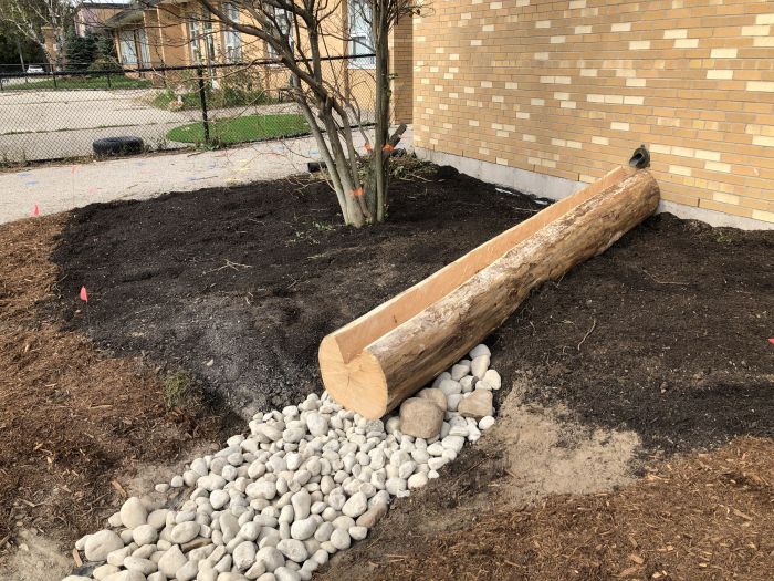
Riprap directing the flow from the log flume into a rain garden at Belfountain P.S., Belfountain, ON. (Photo Source: CVC, 2021)
Riprap conveying the flow from the adjacent field into a rain garden at Janet I. McDougald P.S., Mississauga, ON. (Photo Source: CVC, 2021)


Plant Material Verification and Installation

A healthy and vibrant vegetation structure provides itself with nutrients to sustain growth. Additionally, it holds, and retains water and oxygen, and binds and degrades pollutants. When selecting plants, consider the following:
- Native species need fewer inputs and are better adapted to local climate and soils.
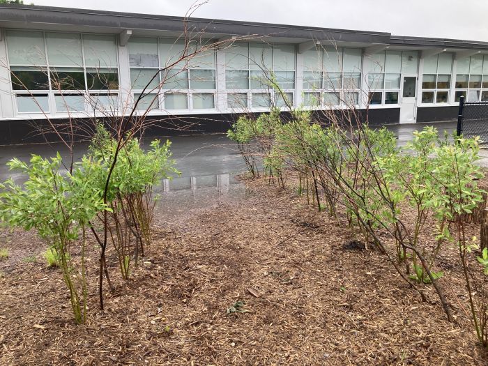
- Larger plant stock should be considered and prioritized in areas of frequent ponding and concentrated flows.
- Trees, shrubs, grasses, sedges and/or rushes present unique benefits and limitations in LID facilities. For example, debris from trees/shrubs may block outlets, but their size and form of planting can provide superior establishment in challenging locations.
- Planted plants in a moderately diverse cluster of plants are more easily maintained and more visually accepted and pleasing to the general public.
- A planting plan should include species that tolerate harsh conditions (e.g., drought, water inundation and/or salt). Most riparian plant species will do well in rain gardens, bioswales and bioretention facilities.

During installation:
- Time of planting: It is crucial for plant survival and thriving, avoid at all times planting during summer months with higher temperatures (July and August) and winter months (November - March). Consider planting early in the spring (April - June) or late in the fall (September - October).
- Planting depth: Plant each plug/tree or shrub to the desired depth as per design considerations. For small plants, it is recommended to use small tools such as a hand trowel.
- Plant substitution: Any changes in the species delivered during construction must be accepted by the designer and/or supervision team before installing.
- Trees/Shrubs protection: If any trees/shrubs need protection, ensure that they receive it by installing proper tree guards.
- Irrigation: It is recommended for the plant material to receive additional watering right after planting if no rainfall event occurs. Also, plant material should be watered during the summer months or during drought periods for two years after planting.
- Fertilizers: The use of these products is acceptable, as long as they are applied properly.
- Pesticides: It is recommended to only use if needed.
For more information regarding plant selection, refer to Plant lists and Plant selection.
Mulch Placement
Wood mulch provides numerous functions to a bioretention practice including reducing soil erosion, filtration, protecting underlying soils from compaction, retaining moisture, and minimizing volunteer weed establishment. Communicate to contractor how to install and the mulch type in the plans and or specifications with notes, details, spot elevations, and other special features needed as per designed.
Equipment recommended for this task can be:
- Automated: Mulch blowers.
- Manual: Shovels, buckets, level rakes.
During installation:
- Ensure that mulch depth should be no greater than 75 mm to maintain oxygen supply to underlying soils.
- Ensure that the top of the mulch meets the finish elevation as per design.
Machinery placing mulch in a rain garden at Glendale Public School in Brampton, ON. Read about the Design and Build Overview in this case study.
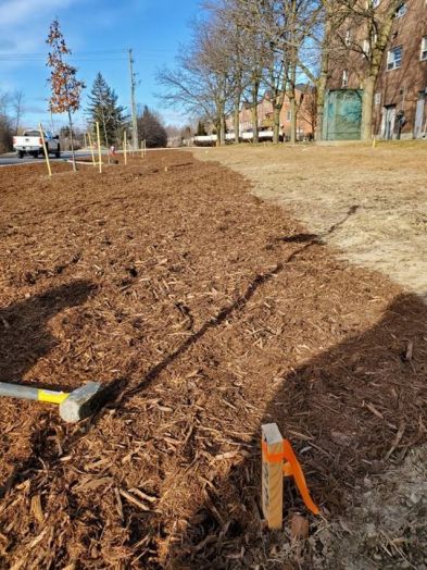
Mulch layer as the final grade in the Haggert Ave bioswale project in Brampton, ON.
Elevation problem with the mulch close to the end of this rain garden at Mineola P.S. This elevation is not allowing runoff to fully enter the rain garden and causing ponding in this low spot.


Stabilizing Contributing Drainage Area - Planting Adjacent Vegetation

Similar to the plant material verification and installation task shown above, any planting required to stabilize the contributing drainage area will need to meet the specifications and considerations shown above.
Additionally, if turf/grass is required to stabilize the contributing drainage area, installation should be done as per the grower/nursery’s specifications and standards.
Finishing Grades: Inlet, Outlet, Biomedia, Plants (JC)[edit]
As-built Survey
Throughout the construction process, it is sometimes necessary to deviate from the intended design of LID features and adapt the design to on-site conditions. The completion of a post-construction as-built survey is a standard operating procedure for engineering projects that captures and changes that were made to the feature’s design during construction.
Survey Steps:
- Use the same datum as the pre-engineering survey
- If a pre-engineering survey is not available, use a reference feature as the datum
- Include data on critical feature elevations and existing utilities, such as:
- Inverts of newly installed pipe
- Vertical and horizontal bends in pipes
- Existing public utilities
- Existing private utilities
- New and existing structures (e.g. catchbasins, manholes, chambers, etc.)
- Identify the type, diameter, and material of exposed utilities
Inspection Points:
- Datum matches the pre-engineering survey or selected reference feature
- Data provided in as-built survey matches the as-built standards of the City
Address Deficiencies and Assumption Protocols (JC)[edit]
Permanent Fencing
Delineating features with permanent fencing can eliminate tripping and falling hazards and protect soil media and plantings.
Construction Steps:
- Securely Install fencing around the perimeter of the feature
Inspection Points:
- Fencing size and material matches design
- Fencing is installed in correct location as per design
Identify and Address Deficiencies
Prior to passing responsibility to the landowner, contractors must ensure that any deficiencies in the LID feature’s construction are addressed. Keep in-mind what mistakes must be avoided during each construction task.
Assumption/Certification
Final inspection requirements are in-place to ensure that a final site-wide inspection is performed and allow for mitigation to occur before the contractor is relieved of responsibility. Final certifications are performed by knowledgeable personnel, such as the design engineer, who are qualified to ensure that LID features are operating as intended. This stage is critically important, as it is the last opportunity for issues to be resolved before the property owner assumes responsibility of the practice. The University of Minnesota and the Minnesota Pollution Control Agency recommend four (4) levels of inspection for final inspections of LID infiltration and filtration practices. The level of inspection, or combination of tests, that is selected is dependent on the goals of the assessment and feasibility of each inspection.
Visual Inspection (Level 1):
This qualitative method is low cost and requires minimal effort to conduct. Visual inspection should be used as an initial step to determine if the LID practice is operating properly. Visual inspections can be performed during dry weather and wet weather to identify situations where water is ponding for longer than intended (24 hours).
Surface Infiltration Capacity Testing (Level 2):
Using infiltrometers or permeameters to measure the hydraulic conductivity at several locations in the LID feature at various times of year can quantitatively verify that the practice can perform as intended.
Synthetic Runoff Testing (Level 3):
To perform the test, the practice must be filled with synthetic runoff and the change in water level must be monitored. Using clean water from a fire hydrant or water truck, synthetic runoff testing can measure the performance of an LID feature in a controlled environment. For this test to be feasible, a series of conditions must be met:
- A water supply that can deliver the required discharge and volume requirements
- The LID feature must be offline
- No precipitation must be expected for 48 hours
- Outflow paths must be temporarily plugged or measured (aside from infiltration)
- The water surface elevation can be measured throughout the test
Long-term Monitoring (Level 4):
Monitoring offers a comprehensive approach to assessing peak flow reduction and water volume reduction. These reductions can be quantified by completing a water budget during natural storm events, specifically through the measurement of inflow and outflow. Long-term monitoring is especially recommended if the LID feature that is the subject of the test is the first of its kind in its given jurisdiction, if geologic conditions pose a concern, or if the feature is being implemented to protect sensitive and significant natural features. It is important to recognize, however, that the unpredictability of natural storm events can lead to inaccuracies in data collection. Furthermore, long-term monitoring generally has the highest cost of the four levels of monitoring.