Wetlands
Overview[edit]

Free-water surface flow wetlands are most commonly employed for stormwater treatment and are similar to SWM ponds in function and design The most significant difference is the extent to which they are designed to incorporate shallow zones for wetland plants. A facility is normally characterized as a wetland if shallow zones (<0.5 m deep) make up more than 70 % of its volume.
Wetlands are an ideal technology for:
- Enhancing biodiversity
- Providing a more aesthetic aquatic landscape
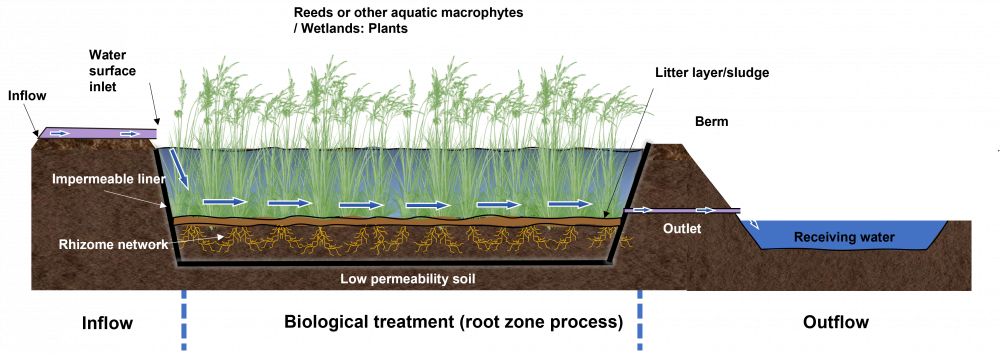
Sub surface flow systems provide generally lower health and safety risks and are sometimes employed to handle stormwater in combination with another wastewater stream.
Planning considerations[edit]
| Free-water surface flow | Horizontal sub-surface flow | Vertical sub-surface flow |
|---|---|---|

|

|

|
Pros
|
Pros
|
Pros
|
Cons
|
Cons
|
Cons
|
Design[edit]
Sizing free-water[edit]
| Element | Design Objective | Criteria |
|---|---|---|
| Drainage Area | Sustaining vegetation, volumetric turnover | 5 Ha (≥10 Ha preferred) |
| Treatment Volume | Provision of appropriate level of protection | See below |
| Active Storage | Detention | Suspended solids settling 24 hrs (12 hrs if in conflict with min. orifice size) |
| Forebay | Pre-treatment |
|
| Length-to-Width Ratio | Maximize flow path and minimize short-circuiting potential |
|
| Permanent pool depth | Vegetation requirements, rapid settling | The average permanent pool depth should range from 150 mm to 300 mm |
| Active storage depth | Storage/flow control, sustaining vegetation | Maximum 1.0 m for storms < 10 year event |
| Side slopes (See also berms) | Safety |
|
| Inlet | Avoid clogging/freezing |
|
| Outlet (See also flow control) | Avoid clogging/freezing |
|
| Maintenance access | Access for backhoes or dredging equipment |
|
| Buffer | Safety | Minimum 7.5 m above maximum water quality/erosion control water level |
.[edit]
| Performance level | Storage volume (m3/Ha) required according to catchment impervious cover | |||
|---|---|---|---|---|
| 35% | 55% | 70% | 85% | |
| 80 % TSS removal | 80 | 105 | 120 | 140 |
| 70 % TSS removal | 60 | 70 | 80 | 90 |
| 60 % TSS removal | 60 | 60 | 60 | 60 |
Modeling sub-surface[edit]
SubWet 2.0 is a modeling tool for sub-surface flow wetlands (both 100% constructed and naturalized/adapted). It can be used to simulate removal of nitrogen (including nitrogen in ammonia, nitrate and organic matter), phosphorus and BOD5 in mg/l and the corresponding removal efficiencies (in %). Although the model has been calibrated already with data from cold and warm climates, users can further calibrate and validate it using local data observations.
Materials[edit]
Planting[edit]
See Wetlands: Plants
Performance[edit]
Relative to a wet pond, a constructed wetland may offer added pollutant removal benefits due to enhanced biological uptake and the filtration effects of the vegetation. Early stage wetlands readily sorb phosphorus onto substrates and sediments. Phosphorus removal in wetland systems is usually carried out by incorporating alum sedimentation ponds or sand filters as cells of the system, and/or by polishing wetland effluent in an iron-dosed mechanical filter.[5]
Freezing temperatures in winter and early spring can reduce treatment if the wetland either freezes solid or a cover of ice prevents the water from entering the wetland. If under-ice water becomes confined, water velocities may increase, thereby reducing contact times[2]. Runoff in excess of maximum design flows should be diverted around the wetland to avoid excessive flows through the wetland.
STEP (under previous name SWAMP) conducted their own research into the performance of stormwater wetlands, the project page and report can be viewed here.
Central Lake Ontario Conservation Authority have been undertaking a coastal wetland monitoring project across Durham region, see here.
Gallery[edit]
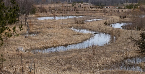
Wetlands on the Rouge River, Toronto ON. Photo credit: Vlad Litvinov (flickr)

Emergent wetland vegetation supported by stormwater runoff at Kino Environmental Restoration Project. Photo by Matthew Grabau, US Fish and Wildlife Service

Azalea Park, Charlottesville VA - "This side of the park, formerly located along a runoff channel that led into Moore's Creek, has been converted into a wetland which supports a surprising amount of insect and amphibian life." -Credit and Photo: Scott Clark (certhia on Flickr).

Walberswick Mill sluice, part of the water level control and coastal defence infrastructure within the marshes, UK


See also[edit]
External links[edit]
- Ontario's wetland conservation strategy
- Centre for Advancement of Water and Wastewater Technologies at Fleming College
Articles for review[edit]
- Kennedy, G., and T. Mayer. 2002. Natural and Constructed Wetlands in Canada: An Overview. Water Qual. Res. J. Canada 37(2): 295–325. doi: 10.2166/wqrj.2002.020.
- Bendoricchio, G., L. Dal Cin, and J. Persson. 2000. Guidelines for free water surface wetland design. EcoSys Bd 8: 51–91. http://www.pixelrauschen.de/wet/design.pdf (accessed 9 May 2018).
- ↑ Grant, N., M. Moodie, and C. Weedon. 2000. Sewage Treatment Solutions. p. 35–67. In Sewage Solutions: Answering the Call of Nature. Centre for Alternative Technology Publications.
- ↑ Jump up to: 2.0 2.1 United States Environmental Protection Agency. 1995. A HANDBOOK OF CONSTRUCTED WETLANDS: A guide to creating wetlands for agricultural wastewater, domestic wastewater, coal mine drainage and stormwater.
- ↑ Jacques Whitford Consultants, 2008. CONSTRUCTED & ENGINEERED WETLANDS p. 1-21
- ↑ Jump up to: 4.0 4.1 Toronto and Region Conservation Authority (TRCA), and CH2M Hill Canada. 2018. Inspection and Maintenance Guide for Stormwater Management Ponds and Constructed Wetlands (T van Seters, L Rocha, and K Delidjakovva, Eds.).
- ↑ Jacques Whitford Consultants, 2008. CONSTRUCTED & ENGINEERED WETLANDS p. 1-21