Difference between revisions of "Monitoring wells: Installation"
Jump to navigation
Jump to search
JamesCowan (talk | contribs) |
|||
| (8 intermediate revisions by 3 users not shown) | |||
| Line 1: | Line 1: | ||
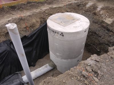
[[File:monitoring-well-subgrade.jpg|400px|thumb|right|Monitoring well stack installed next to underdrain within the LID practice.]] | [[File:monitoring-well-subgrade.jpg|400px|thumb|right|Monitoring well stack installed next to underdrain within the LID practice. (Photo Source: CVC, 2010)]] | ||
[[Monitoring wells]] allow for measurement of water levels in the sub-surface components of LID practices. They are important for sampling procedures and ensuring that the LID feature are performing as intended. | |||
[[Monitoring wells]] allow for measurement of water levels in the sub-surface components of LID practices. They are important for sampling procedures and ensuring that the LID feature are performing as intended. | |||
'''Construction Steps:''' | '''Construction Steps:''' | ||
#Install a cap stand at the required elevation to anchor the monitoring well. | #Install a cap stand at the required elevation to anchor the monitoring well. | ||
#Wrap the perforated pipe with a geotextile sock (to prevent migration of soil into the well). | #Wrap the perforated pipe with a geotextile sock (to prevent migration of soil into the well). | ||
#Anchor the perforated pipe to the bottom of the LID feature. | #Anchor the perforated pipe to the bottom of the LID feature. | ||
#Install a lockable cap to the top of the standpipe to protect against vandalism. | #Install a lockable cap to the top of the standpipe to protect against vandalism. | ||
#Install monitoring equipment (e.g., a level logger) if required. | #Install monitoring equipment (e.g., a level logger) if required. | ||
'''Key Inspection Points:''' | '''Key Inspection Points:''' | ||
*Pipe is perforated, rigid, and matches design specifications. | *Pipe is perforated, rigid, and matches design specifications. | ||
*Well is installed according to contract documents. | *Well is installed according to contract documents. | ||
*Geotextile sock is wrapped around the perforated portion of the well. | *Geotextile sock is wrapped around the perforated portion of the well. | ||
'''Mistakes to Avoid:''' | '''Mistakes to Avoid:''' | ||
*Incorrect sequencing | *Incorrect sequencing: Ensure that standpipe is installed prior to backfilling with granular material. | ||
Latest revision as of 21:45, 22 September 2022
Monitoring wells allow for measurement of water levels in the sub-surface components of LID practices. They are important for sampling procedures and ensuring that the LID feature are performing as intended.
Construction Steps:
- Install a cap stand at the required elevation to anchor the monitoring well.
- Wrap the perforated pipe with a geotextile sock (to prevent migration of soil into the well).
- Anchor the perforated pipe to the bottom of the LID feature.
- Install a lockable cap to the top of the standpipe to protect against vandalism.
- Install monitoring equipment (e.g., a level logger) if required.
Key Inspection Points:
- Pipe is perforated, rigid, and matches design specifications.
- Well is installed according to contract documents.
- Geotextile sock is wrapped around the perforated portion of the well.
Mistakes to Avoid:
- Incorrect sequencing: Ensure that standpipe is installed prior to backfilling with granular material.
