Bioretention: Sizing
This article is specific to bioretention, vegetated systems that infiltrate water to the native soil.
If you are designing a planted system which does not infiltrate water, see advice on Planters: Sizing.
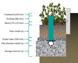
Many of the dimensions in a bioretention system can be predetermined according to the function of the component. There is greatest flexibility in the ponding depth and the depth of the storage reservoir beneath the optional underdrain pipe. The order of operations in calculating these dimensions depends on whether an underdrain is desired.
| Component | Recommended depth (with underdrain pipe) | Recommended depth (no underdrain pipe) | Typical void ratio (VR) |
|---|---|---|---|
| Ponding (dp) | 300 mm | See below | 1 |
| Mulch | 75 ± 25 mm |
| |
| filter media (dm) |
|
| |
| Choker course | 100 mm | 0.4 typical | |
| Perforated pipe and surrounding aggregate | Is equal to underdrain pipe diameter | Not applicable | 0.4 |
| Storage reservoir (ds) | See below | See below | 0.4 |
Calculate the maximum overall depth[edit]
- Step 1: Determine what the planting needs are and assign appropriate depth of media, using the table above.
- Step 2: Select an underdrain pipe diameter (typically 100 - 200 mm), assign this as an 'embedding' depth. *Note that this component does not apply if a downstream riser is being used to control an extended saturation zone.
- Step 3: Calculate the maximum permissible water storage depth beneath the pipe (ds, max, mm):
Where:
- f' = Design infiltration rate (mm/hr), and
- t = Drainage time (hrs). Check local regulations for drainage time requirements.
Additional step for system without underdrain[edit]
- Step 4: Determine maximum permissible ponding depth (dp, max):
Where:
- f' = Design infiltration rate (mm/hr), and
- 48 = Maximum permissible drainage time for ponded water (hrs)
- Note that in designs without underdrains, conceptually the drainage of ponded water is limited by exfiltration at the base of the practice.
- Step 5: Sum total depth of bioretention, and compare to available depth between the surface grade and the seasonally high water table and/or bedrock elevations. Adjust if necessary.
Calculate the remaining dimensions[edit]
- Step 6: Multiply the depth of each separate component by the void ratio and then sum the total to find the 1 dimensional storage (in mm).
- Step 7: Calculate the required total storage (ST, m3):
Where:
- RVCT is the Runoff volume control target (mm),
- Ac is the catchment area (Ha), and
- 10 is the units correction between m3 and mm.Ha.
- Step 8. Divide required storage (m3) by the 1 dimensional storage (in m) to find the required footprint area (Ap) for the bioretention in m2.
- Step 9. Calculate the peak flow rate through the perforated pipe,
- Step 10. Calculate the peak flow rate through the filter media,
- Step 11. Determine if downstream flow control is required to achieve hydrologic objectives.
Additional calculations[edit]
Calculating infiltration practice drainage in 1 dimension[edit]
This spreadsheet compares drainage in a single dimension under zero head conditions, mean head conditions and falling head conditions. It provides a more conservative measurement of the drainage time for the purposes of groundwater mounding (where a shorter drainage time causes a greater impact).
Drainage time (3D)[1][edit]
In some situations, it may be desirable to reduce the size of the bioretention required, by accounting for rapid drainage. Typically, this is only worth exploring over sandy soils with rapid infiltration.
Note that narrow, linear bioretention features (or bioswales) drain faster than round or blocky footprint geometries.
- Begin the drainage time calculation by dividing the area of the practice (Ap) by the perimeter (P).
- To estimate the time (t) to fully drain the facility:
Where:
- VR is the void ratio of the media,
- Ap is the area of the practice (m2),
- f' is the design infiltration rate (mm/hr),
- P is the perimeter of the practice (m), and
- dT is the total depth of the practice, including the ponding zone (m).
Groundwater mounding[edit]
When you wish to model the extent of groundwater mounding beneath an infiltration facility. This tool uses Hantush's derivation (1967).
Note that this is a minor adaptation (metric units and formatting) from the original tool, written and hosted by the USGS.
- ↑ Woods Ballard, B., S. Wilson, H. Udale-Clarke, S. Illman, T. Scott, R. Ahsley, and R. Kellagher. 2016. The SuDS Manual. 5th ed. CIRIA, London.


![{\displaystyle t={\frac {V_{R}A_{p}}{f'P}}ln\left[{\frac {\left(d_{T}+{\frac {A_{p}}{P}}\right)}{\left({\frac {A_{p}}{P}}\right)}}\right]}](https://wikimedia.org/api/rest_v1/media/math/render/svg/7b7b4e8cd53033eb0099c43f67d3bf6288311655)