User talk:Sahlla Abbasi
Overview[edit]
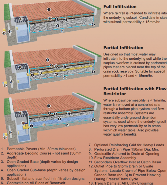
Permeable pavements are an alternative to conventional impervious pavement that allows stormwater to drain through the surface and into a stone reservoir, where it infiltrates into the underlying native soil or is temporarily detained. Depending on the native soil properties and physical constraints, the system may be designed with no underdrain for full infiltration, with an underdrain for partial infiltration, or with an impermeable liner and underdrain for a non-infiltrating, or detention and filtration only practice.
Permeable pavement types include:
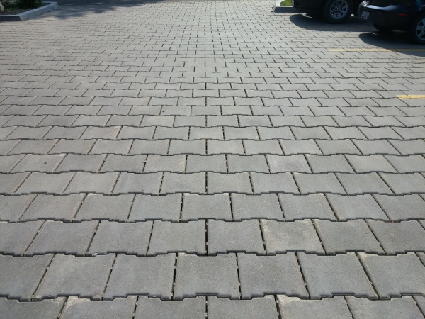
- Permeable interlocking pavers (concrete and composite materials)
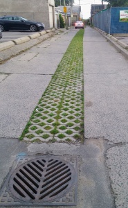
- Permeable grid systems (concrete or composite materials)
- Permeable articulated block systems
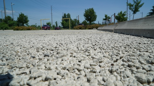
- Pervious concrete (poured-in-place or pre-cast)
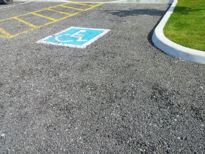
- Porous asphalt
Permeable paving is ideal for:
- Sites with limited space for other surface stormwater BMPs
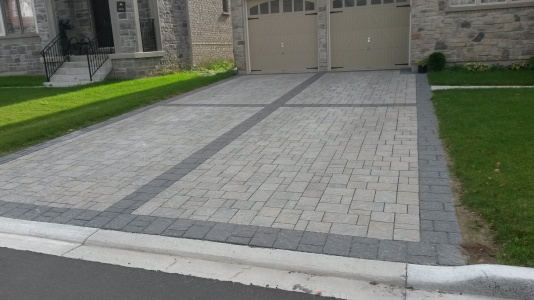
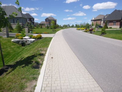
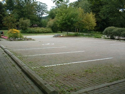
- Projects such as low traffic roads, parking lots, driveways, pedestrian plazas and walkways
The fundamental components of a permeable paving system are:
- Pavement surface: interlocking pavers with open joints, grid systems, precast pervious slabs or pavers, poured in place asphalt or concrete Bedding layer as a levelling course (for precast systems)
- Subsurface base storage reservoir of open graded aggregate
- Edge restraints
Additional components may include:
- an underdrain system
- geotextile, at the discretion of design professional
- impermeable geomembrane on sites where soil infiltration is not desired
- geo-grids for sites with heavy vehicle loading
- monitoring wells and clean-outs
Planning considerations[edit]
Infiltration[edit]
Permeable pavements can be constructed over any soil type, but hydrologic soil group (HSG) A and B are best for achieving water balance objectives. Native soil infiltration rate at the proposed facility location and depth should be confirmed through in-situ measurements of hydraulic conductivity under field saturated conditions. A liner will be required if native soils are contaminated.
Systems located in low permeability soils with an infiltration rate of less than 15 mm/hr (i.e., hydraulic conductivity of less than 1x10⁻⁶ cm/s), require incorporation of a perforated pipe underdrain. Pavements require an impermeable geomembrane where the underlying soils are contaminated or the pavement is within two year time-of-travel wellhead protection area (see local drinking water source protection plan)
Space[edit]
Permeable pavements can be used for the entire parking lot, driveway or road surface, or be designed to to receive runoff from adjacent impervious surfaces. For example, the parking spaces of a parking lot or road can be permeable pavements while the drive lanes are conventional asphalt. The impervious area draining on to the permeable pavement should not exceed the area of the permeable pavement itself. Relatively clean drainage areas such as roofs may be up to 4 times the size of the pavement but should include filtration pretreatment to remove coarse debris prior to being conveyed directly to the storage reservoir.
Permeable pavements should be located down-gradient from building foundations. If the pavement does not receive drainage from other surfaces, no setback is required. If the pavement receives drainage from other surfaces a minimum setback of four metres down-gradient is recommended. A smaller setback may be permissible where foundations are protected by a geomembrane.
Site Topography[edit]
Permeable pavement surface slope should be at least 1% and no greater than 5%. Steeper slopes may require additional features (see subgrade section below). Pervious areas should not drain onto permeable pavements.
Groundwater[edit]
Maintaining a separation of one metre between the elevations of the base of the practice and the seasonally high water table, or top of bedrock is recommended. Lesser or greater values may be considered based on groundwater mounding analysis. See Groundwater page for further guidance and a spreadsheet tool.
To protect groundwater from possible contamination, runoff from pollution hot spots should not be treated by permeable pavements designed for full or partial infiltration. Facilities designed with an impermeable liner (filtration-only) can be used. Also see the Site considerations page.
Private Sites[edit]
If permeable paving systems are installed on private lots, property owners or managers will need education on their routine maintenance needs, understanding the long-term maintenance plan. They may also be subject to a legally binding maintenance agreement. An incentive program, such as a storm sewer user fee based on the area of impervious cover on a property that is directly connected to a storm sewer, could be used to encourage property owners or managers to maintain existing practices.
Design[edit]
Subgrade[edit]
For infiltrating pavements, subgrade slopes should be minimized so that runoff will be able to infiltrate evenly through the entire surface. For steeply sloped sites (>5%), check dams, berms or weir structures on the native soils of the pavement should be considered. If the system is not designed for infiltration, the bottom should be sloped at 1 to 5% toward the underdrain. Subgrades should be compacted to 95% Standard Proctor Density. If a lesser value is desired to promote infiltration, a thicker sub-base should be considered. Subgrade soils should not be scarified.
Pretreatment[edit]
In most designs, the permeable surface acts as pretreatment to the storage reservoir below. Since sediment accumulates in the permeable areas of the pavement, periodic vacuum sweeping and preventative measures like not storing snow, construction materials or landscaping materials on the pavement are critical to prevent clogging.
Underdrain[edit]
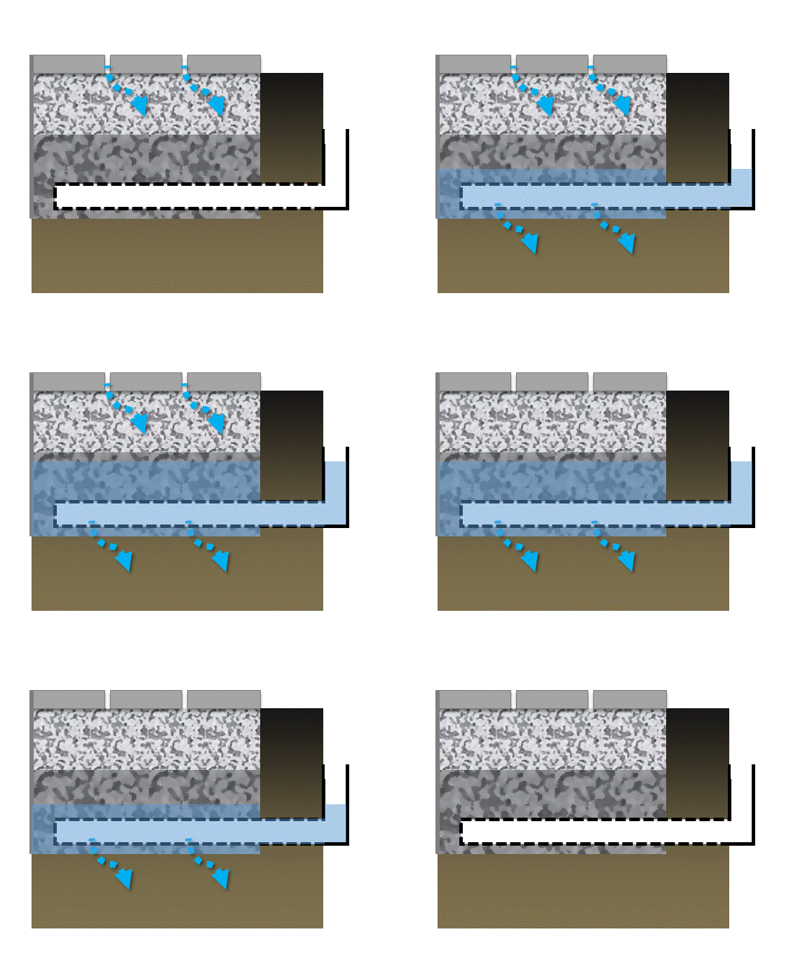
The diagram below displays permeable pavement cross sections showing full and partial infiltration designs.[1] See Underdrains page for further guidance.
Access Structures[edit]
Access structures are used for periodic inspection and flushing. It could be a maintenance hole or vertical standpipe connected to the perforated pipe. For accessing the underdrain pipe with camera or cleaning equipment, 45° couplings should be used for standpipe connections.
Overflow[edit]
All designs require an overflow outlet connected to a storm sewer with capacity to convey larger storms. This is normally achieved with a catch basin outlet, but water may also be directed to a downstream practice (e.g. bioretention, swale). Another option is a gravel diaphragm or trench along the downgradient edge of the pavement that drains to the storage reservoir below.
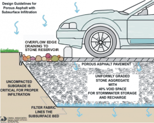
The diagram to the left is an example of a porous asphalt system with overflow edge draining to a reservoir.[2] A flush curb extending into the base may be required as an edge restraint for some permeable pavement types. Decorative stone is lined with a geotextile to prevent migration of fine sediment into the pavement base and facilitate maintenance.
Finish course[edit]
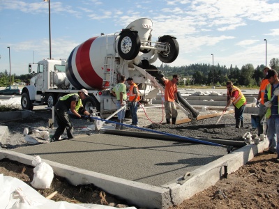
Consult the manufacturer for the design specifications of their product. In pervious concrete and porous asphalt systems, the concrete or asphalt mix specifications and construction procedures are key to proper functioning. These systems require well-trained and experienced contractors for installation.
| Material | Specification | Quantity |
|---|---|---|
| Pervious concrete |
|
Thickness will range from 100 mm - 150 mm depending on the expected loads. |
| Porous asphalt |
|
Thickness will range from 50 mm - 100 mm depending on the expected loads. |
| Permeable Interlocking Pavements |
|
|
| Stone Resevoir |
100 revolutions and maximum of 50% for 500 revolutions
|
|
| Geotextile |
|
|
| Underdrain (optional) |
|
Pipes should terminate 0.3 m short from the sides of the base. |
Foundation Aggregates[edit]
All aggregates should meet the following criteria:
- Porosity of 0.4
- Maximum wash loss of 0.5%
- Minimum durability index of 35
- Maximum abrasion of 10% for 100 revolutions and maximum 50% for 500 revolutions
Most OPSS aggregates are not recommended for use in permeable pavements, with the exception of 'Granular O' type.
Granular Subbase Should be clear, crushed 50 mm diameter stone, graded in accordance with ASTM D2940. 'Rain ballast' aggregate (63 mm) would also be suitable
Granular Base Should be clear, crushed 20 mm diameter stone conforming to ASTM C33 No 57
Bedding Should be clear, crushed 5 mm diameter stone, graded in accordance with ASTM C33 No 8, High Performance Bedding (1-9 mm diameter), or equivalent. Typical bedding thickness is between 40 mm and 75 mm.
For more information, also see Aggregates page.
Sizing Stone Reservoirs[edit]
The stone reservoir must meet both runoff storage and structural support requirements. The bottom of the reservoir should be level so that water infiltrates evenly.
Geotextile[edit]
Geotextiles are non-woven needle punched, or woven monofilament geotextile fabric that may be placed between the storage reservoir and native soil to maintain separation. Geotextiles are commonly used on low strength soils (CBR <4). Where expansive clays are present, a non-infiltrating design may be necessary. If used, geotextile socks around perforated pipes should conform to ASTM D6707 with minimum water flow rate conforming to ASTM D4491 (12,263 L/min/m2 at 5 cm head).
Edge Restraints[edit]
Pavers must abut tightly against the restraints to prevent rotation under load and any consequent spreading of joints. The restraints must be able to withstand the impact of temperature changes, vehicular traffic and snow removal equipment. Metal or plastic stripping is acceptable in some cases, but concrete curbs are preferred. Concrete curbs should be supported on a minimum base of 150 mm of aggregate.
Landscaping[edit]
Adjacent landscaped areas should drain away from permeable pavement to prevent sediments from running onto the surface. Urban trees also benefit from being surrounded by permeable pavement rather than impervious cover, because their roots receive more air and water.
Monitoring Wells: see “Deeper Wells” section
Heavy Vehicle Traffic[edit]
Permeable paving is not typically used in locations subject to heavy loads. However, some permeable pavements are designed for heavy loads and have been used in commercial port loading and storage areas. A flexible geogrid structure may be used to improve the structural capacity of the pavement by spreading loads over a larger area. Increasing the base thickness will also improve structural capacity.
Modeling permeable paving in the Treatment Train Tool[edit]
Construction Considerations[edit]
Properly installed permeable pavement requires trained and experienced construction contractors. The following general recommendations apply:
- Sediment Control: The treatment area should be fully protected during construction so that no sediment reaches the permeable pavement system. Construction vehicle traffic should not be permitted on the permeable pavement and its drainage areas once the pavement has been installed.
- Base Construction: Aggregate should be placed in 100 mm to 150 mm lifts and compacted with a minimum 9 ton steel drum vibratory roller. A light weight deflectometer may be used to test compaction level of open graded stone and compare to specifications.
- Weather: Porous asphalt and pervious concrete require a specific temperature range to set properly and the setting time can be several days[3].
Inspection and Maintenance[edit]
Permeable pavements require regular inspection and maintenance to ensure proper functioning. The limiting factor for permeable pavements is clogging of the surface course or joint filler between pavers. As these start to fill, the trapped sediment becomes finer and finer until they eventually become clogged. Ideally, signs should be posted on the site identifying permeable pavement. This can also serve as a public awareness and education opportunity. See: Permeable pavement: Maintenance
Life Cycle Costs[edit]
Initial construction costs for permeable pavements are typically higher than conventional asphalt pavement surfaces, largely due to the price of the surface course and thicker aggregate base needed for stormwater storage. However, the cost difference is reduced or eliminated when total life-cycle costs, or the total cost to construct and maintain the pavement over its lifespan, are considered. Other potential savings and benefits include reduced need for storm sewer pipes and other stormwater practices, less developable land consumed for stormwater treatment, and ancillary benefits (improved aesthetics and reduced urban heat island effect). These systems are especially cost effective in existing urban development where parking lot expansion is needed, but there is not sufficient space for other types of BMPs. They combine parking, stormwater infiltration, retention, and detention into one facility. See also: Cost analysis resources
Performance[edit]
| BMP | Water Balance | Water Quality | Erosion Control |
|---|---|---|---|
| Permeable pavement with no underdrain | Yes | Yes-size for water quality storage requirement | Partial-based on available storage volume and native soil infiltration rate |
| Permeable pavement with underdrain | Partial-based on available storage, native soil infiltration rate and if a flow restrictor is used | Yes-size for water quality storage requirement | Partial-based on available storage, native soil infiltration rate and if a flow restrictor is used |
| Permeable Interlocking Pavements | No-some volume reduction occurs through evaporation | Yes-size for water quality storage requirement | Partial-based on available storage volume and if a flow restrictor is used |
Water Balance[edit]
Research on the volumetric runoff reduction performance of permeable pavements have been conducted on pavements with and without an underdrain in the base. Volumetric performance improves when:
- Native soils have high infiltration capacity.
- Impervious surface draining onto the permeable pavement is limited or absent.
- Underdrain is elevated above the native soil and/or a flow restrictor is installed on the underdrain.
All permeable pavements have very high surface infiltration rates when appropriately maintained. Therefore, the surface course type (i.e. PICP, pervious concrete) is not a key factor in determining volumetric runoff reduction performance.
| LID Practice | Location | Runoff Reduction* | Reference |
|---|---|---|---|
| Permeable pavement without underdrain | Guelph, Ontario | 90% | James (2002)[4] |
| Pennsylvania | 90% | Kwiatkowski et al. (2007)[5] | |
| France | 97% | Legret and Colandini (1999)[6] | |
| Washington | 97 to 100% | Brattebo and Booth (2003)[7] | |
| Connecticut | 72%* | Gilbert and Clausen (2006)[8] | |
| King City, Ontario | 99%* | TRCA (2008) | |
| Permeable pavement with underdrain | |||
| Vaughan, Ontario | 45%2 | Van Seters and Drake (2015) | |
| North Carolina | 98 to 99% | Collins et al. (2008)[9] | |
| United Kingdom | 50% | Jefferies (2004)[10] | |
| United Kingdom | 53 to 66% | Pratt et al. (1995)[11] | |
| Maryland | 45% to 60% | Schueler et al. (1987)[12] | |
| Mississauga | 61 to 99% | CVC (2018) | |
| Runoff Reduction Estimate* | 85% without underdrain;
45% with underdrain | ||
Water Quality[edit]
Like other stormwater practices, the water quality performance of permeable pavements is closely tied to the reduction of runoff volumes through infiltration, However, permeable pavements are also very effective stormwater runoff filters. Most sediments and associated contaminants are trapped within the surface pores or gravel filled joints between the pavers. A five year study of three permeable pavement surfaces in Vaughan showed total suspended solids (TSS) concentration reductions between 88 and 89% (Van Seters and Drake, 2015). Other STEP studies in the Greater Toronto Area have displayed similar results, with only 7% of 181 permeable pavement effluent samples having TSS concentrations above 30 mg/L (median = 7 mg/L)TRCA, 2015.
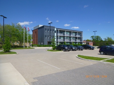
Another group of studies of permeable pavements examines the quality of water infiltrated through soils beneath the installations. In these studies the quality of infiltrated water is used as a measure of the potential for contamination of groundwater. One such study of a permeable interlocking concrete pavement installed in a college parking lot in King City, Ontario, showed that stormwater infiltrated through a 60 cm granular reservoir and 1 metre of native soil had significantly lower concentrations of several typical parking lot contaminants relative to runoff from an adjacent asphalt surface (TRCA, 2008). These results are consistent with research on the quality of infiltrated water from permeable pavements in Washington[7] and Pennsylvannia[5]. As with all stormwater infiltration practices, risk of groundwater contamination from infiltration of runoff laden with road de-icing salt constituents (typically sodium and chloride) may be a concern in lands designated as source protection areas. Chloride ions are extremely mobile in the soil and are readily transported by percolating water to aquifers.
Stream Channel Erosion[edit]
Permeable pavements help address stream erosion and flood flows by attenuating peak flows through temporary storage and release. A STEP study in Vaughan showed a 91% peak flow reduction due in part to flow restriction on the underdrain (Van Seters and Drake, 2015). A later study of three permeable pavements in a parking lot in Mississauga showed peak flow reductions between 39 and 84% for events greater than 25 mm (CVC, 2018).
Other Benefits[edit]
- Winter Performance: Snow plow and deicing costs are reduced due to rapid drainage of snow melt. Puddling on parking lots is also reduced. A two year study of PICP in Vaughan found that the PICP provides equivalent or higher levels of safety compared with asphalt when treated with de-icing products at medium (0.049 kg/m2) or low (0.024 kg/m2) salt application rates[13].
- Urban Heat Island Effect Reduction: Porous materials have less thermal conductivity and thermal capacity than traditional impervious pavement, thereby reducing the urban heat island effect [14]. Year round measurements of asphalt and PICP surface temperatures in King City, Ontario showed asphalt temperatures above 20°C approximately 12% more often than the adjacent permeable pavers (TRCA, 2008).
- Improved Street Tree Health: Permeable pavements installed around tree planting zones in hardscapes help provide air and water to root systems, thereby contributing to healthier, longer lasting trees that require less manual irrigation.
- Quiet Streets: Porous asphalt surfaces absorb sound energy and dissipate air pressure around tires before any noise is generated. Tire noise is lower in loudness and pitch for a porous surface than a corresponding dense pavement [14]. Segmented pavers do not share this benefit and are generally noisier than asphalt roads.
- LEED Credits: Permeable pavement has the potential for earning Canadian Green Building Council LEED sustainable sites credits for reducing stormwater pollution and runoff, urban heat island mitigation, and conservation of materials and resources.
Proprietary Links[edit]
In our effort to make this guide as functional as possible, we have decided to include proprietary systems and links to manufacturers websites.
Inclusion of such links does not constitute endorsement by the Sustainable Technologies Evaluation Program.
Lists are ordered alphabetically; link updates are welcomed using the form below.
Pre-cast with joints[edit]
- Eco-Optioc, Unilock
- Enviro Pavers, Oaks
- Pavedrain, distributed by Nilex
- Terra flo, Santerra
- Various Products, Permacon
Pre-cast pervious[edit]
Cast in place[edit]
Plastic grid[edit]
Gallery[edit]
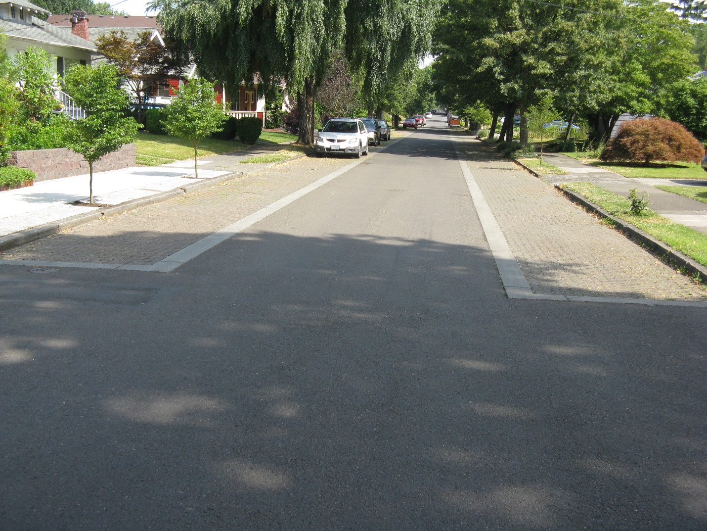
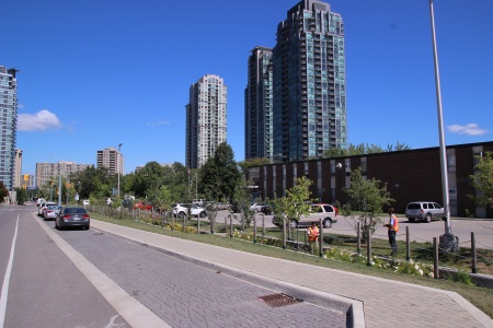
Permeable pavers in parking bays, Mississauga ON (note inspection of bioretention occurring in the background)
Inspection wells should be located at the edges or even off the side of permeable pavement areas
- ↑ Greater Vancouver Regional District (GVRD). 2005. Stormwater Source Control Design Guidelines 2005. Prepared by Lanarc Consultants Limited, Kerr Wood Leidal Associates Limited and Goya Ngan.
- ↑ Pennsylvania Department of Environmental Protection (PDEP). 2006. Pennsylvania Stormwater Best Management Practices Manual. Prepared by Cahill Associates Inc., Harrisburg, PA.
- ↑ City of Portland. 2004. Portland Stormwater Management Manual. Prepared by the Bureau of Environmental Services (BES). Portland, OR.
- ↑ James, W. 2002. Green Roads: Research into Permeable Pavers. Stormwater. March/April.
- ↑ 5.0 5.1 Kwiatkowski, M., Welker, A.L., Traver, R.G., Vanacore, M., Ladd. T. 2007. Evaluation of an infiltration best management practice utilizing pervious concrete. Journal of the American Water Resources Association. Vol. 43. No. 5. pp. 1208-1222.
- ↑ Legret, M and V. Colandani. 1999. Effects of a porous pavement structure with a reservoir structure on runoff water: water quality and fate of metals. Water Science and Technology. 39(2): 111-117
- ↑ 7.0 7.1 Brattebo, B. and D. Booth. 2003. Long term stormwater quantity and quality performance of permeable pavement systems. Water Research 37(18): 4369-4376
- ↑ Gilbert, J. and J. Clausen. 2006. Stormwater runoff quality and quantity from asphalt, paver and crushed stone driveways in Connecticut. Water Research 40: 826-832.
- ↑ Collins, K., W. Hunt and J. Hathaway. 2008. Hydrologic comparison of four types of permeable pavement and standard asphalt in eastern North Carolina. Journal of Hydrologic Engineering.
- ↑ Jefferies, C. 2004. Sustainable drainage systems in Scotland: the monitoring programme. Scottish Universities SUDS Monitoring Project. Dundee, Scotland
- ↑ Pratt, C.J., Mantle, J.D.G., Schofield, P.A. 1995. UK research into the performance of permeable pavement reservoir structures in controlling stormwater discharge quantity and quality. Water Science Technology. Vol. 32. No. 1. pp. 63-69.
- ↑ Schueler, T. 1987. Controlling urban runoff: a practical manual for planning and designing urban BMPs. Metropolitan Washington Council of Governments. Washington, DC.
- ↑ Marvin, J., Scott, J., Van Seters, T., Bowers, B., Drake, J. Winter Maintenance of Permeable Interlocking Concrete Pavement: Evaluating Opportunities to Reduce Road Salt Pollution and Improve Winter Safety, submitted to Transportation Research Record May 2020, under review
- ↑ 14.0 14.1 Ferguson, B.K. 2005. Porous Pavements. Integrative Studies in Water Management and Land Development. Taylor and Francis: New York.
