Difference between revisions of "Bioretention: Construction"
Kyle menken (talk | contribs) |
Kyle menken (talk | contribs) |
||
| Line 124: | Line 124: | ||
- Do constructability issues require a field change or amendment to the tender? | - Do constructability issues require a field change or amendment to the tender? | ||
|} | |} | ||
''' | |||
'''ESC Inspection and Maintenance | '''Tendering and contract''' <br> | ||
'''Communication, inspection plan, and utility coordination'''<br> | |||
'''Erosion and sediment controls, construction limits, natural heritage protection, and perimeter controls'''<br> | |||
'''ESC Inspection and Maintenance'''<br> | |||
===Excavation and Mass Grading (KM)=== | ===Excavation and Mass Grading (KM)=== | ||
Revision as of 18:08, 29 June 2022
This section is also applicable to:
Construction Tasks Table[edit]
| Construction Stage | Construction Task | Bioretention | Bioswale | Rain garden |
|---|---|---|---|---|
| Pre-Construction | Verification of Siting and LID Design | x | x | x |
| Communication and Utilities Coordination | x | x | x | |
| Installation of ESC and Construction Fencing | x | x | x | |
| ESC Inspection and Maintenance (ongoing) | x | x | x | |
| Excavation and Mass Grading |
Clearing and Grubbing | x | x | x |
| Excavation | x | x | x | |
| Rough Grade | x | x | x | |
| Verification of Grading/Survey* | x | x | x | |
| Scarification (if applicable) | x | x | x | |
| Backfill Granular, Utilities and Pipes |
Geotextile (if applicable) | x | x | x |
| Impermeable Liner (if applicable) | x | x | ||
| Underdrain (if applicable) | x | x | ||
| Overflow or Overflow Drain (if applicable) | x | x | x | |
| Monitoring Well (if applicable) | x | x | ||
| Clean Out Port | x | x | x | |
| Storage Reservoir | x | x | ||
| Stone Choker Layer (if applicable) | x | x | ||
| Curbing (if applicable) | x | x | ||
| Pre-treatment and Inlet | x | x | x | |
| Soil/Filter Media | x | x | x | |
| Finishing Grades: Inlet, Outlet, Biomedia and Plants |
Finishing Grading | x | x | x |
| Riprap/Large Stone (if applicable) | x | x | x | |
| Plant Verification and Installation | x | x | x | |
| Mulch Placement | x | x | x | |
| Stabilizing Contributing Drainage Area - Planting Adjacent Vegetation |
x | x | x | |
| As-built Survey | x | x | ||
| Permanent Fencing (if applicable) | x | x | ||
| Post-Construction | Identify and Address Deficiencies | x | x | x |
| Assumption/Certification Protocols | x | x | x |
Construction Tasks Described[edit]
Pre-Construction (KM)[edit]
Design verification and site walk-through
| Verification point | Key considerations |
|---|---|
| Adjacent land uses | - Have land uses changed while the design was in progress? Are there any planned land-use changes on adjacent properties and is their drainage connected to the site soon to be under construction?
- Will it create dirty runoff that may flow onto the construction site or into the LID feature? - Is additional ESC required beyond what is marked in the ESC plan? |
| Contributing and receiving drainage areas | - Where is water coming onto the site and where is water leaving the site?
- Are any environmentally sensitive areas downstream? - Are there any apparent changes while the design was in progress? If so, should these changes necessitate modifications to the design, particular ESC measures, etc.? |
| Seasonal maintenance operations | - Will winter snow storage and salt application impact the functionality of the LID feature? |
| Location of LID features | - Do the proposed LID locations match the site?
-Does the footprint of the LID fit within the site constraints? |
| Existing and planned infrastructure / utilities | - Confirm accuracy of design drawings
- Are there any unmarked utilities not detailed within drawing set? |
| Property boundaries and building foundations | - Confirm accuracy of design drawings
- Do fence lines align with property boundaries? |
| Natural heritage features and existing vegetation | - Do the designs accurately capture existing natural heritage features? Which areas on the site should be protected during construction, and will these exclusion areas make the LID facility more difficult to construct? Where are the tree drip lines?
- Are there any invasive species on the site which could colonize the LID practice? |
| Access, sequencing, staging, and constructability | - Where will the contractor access the site?
- If applicable, where can materials and/or equipment be stored - What is the ideal construction sequence, and where could materials and supplies be stored during construction? - Do site characteristics constrain standard construction practices? Will it be a difficult job? - Do constructability issues require a field change or amendment to the tender? |
Tendering and contract
Communication, inspection plan, and utility coordination
Erosion and sediment controls, construction limits, natural heritage protection, and perimeter controls
ESC Inspection and Maintenance
Excavation and Mass Grading (KM)[edit]
Clearing and Grubbing
Excavation
Rough Grade
Verification of Grading/Survey*
Scarification
Backfill Granular and Pipes (JC)[edit]
Geotextile

Geotextiles are filter fabrics that can be installed to separate dissimilar soils and prevent the migration of materials. As such, proper installation of geotextiles is important for ensuring the proper division of materials.
Construction Steps:
- Roll out fabric on the flattened sub-grade surface
- Provide a minimum overlap of 300 mm between adjacent lengths of geotextile. If the manufacturer specifies a greater overlap, follow the manufacturer’s specification
- Fabric should be secured in place with stakes along the edge of the sub-grade surface and where lengths of fabric overlap
- Provide 500 mm of excess at the ends of each length of fabric
- Excess material should be folded on top of the infiltration medium/choker course once installed
- Provide cuts for trees where appropriate
Key Inspection Points:
- Geotextile is clean and free of damage
- Geotextile delivered to the site matches the design specifications and is approved by the engineer prior to installation
- Sufficient overlap is provided between lengths of fabric
- Geotextiles have been applied as per the manufacturer’s guidelines
- Structural considerations for geotextiles have been made when applied adjacent to infrastructure and the geotextile can handle expected structural loads
- Class II geotextiles conform to OPSS 1860
Mistakes to Avoid:
- Wrinkles in the fabric – follow the manufacturer’s procedure for installation to ensure geotextiles lie smooth on sub-grade
- Unnecessary application of geotextile – mixing of media is negligible where structural loads are not expected, so geotextile does not need to be applied. Also geotextiles should not be used where root growth is encouraged to penetrate different layers of media
For more information on geotextiles, see the page on geotextiles.
Underdrains
Underdrains are pipes that can be included to collect subsurface water. Their design is determined by the drainage requirements of the feature.
Construction Steps:
- Install the underdrain to grade with a consistent slope of 0.5% to 1.0%
- Connect overflow risers with single-elbowed ‘y’ connections or 45° elbows
- Situate maintenance risers where siltation is expected in drain lines (such as at junctions or where grade and direction changes occur)
- Mark the locations of risers
- Use video inspections to confirm that the interior of the underdrain remains free of debris after construction
Key Inspection Points:
- Size, type, and material of the underdrain conforms to the design specifications
- Underdrain is perforated prior to arrival on-site
- Drain material is resistant to UV radiation and any chemicals in the soil and groundwater
- Clean-outs are positioned correctly and spaced appropriately for the size of the underdrain
- Any manual perforations are approved by the engineer
- Pipe grade matches design specifications
- Tie-in locations to municipal sewers meet City specifications
Mistakes to Avoid:
- Incorrect overflow risers – ensure single-elbowed ‘y’ connections or 45° elbows are used for overflow risers instead of ‘T’ connections
- Incorrect drain size – confirm underdrain has an internal diameter greater than or equal to 200 mm to reduce freezing and allow cleaning and camera inspections
- Potential for clogging – Remove sock from underdrain prior to installation
For more information on the design of under-drains, see the page on under-drains.
Impermeable Liners

Impermeable liners can be applied when LID features are not intended to infiltrate runoff into the underlying soil. Where building foundations that are adjacent to the LID feature are not waterproofed, liners can be used to protect neighbouring infrastructure.
Construction Steps:
- Compact 30 – 50 mm of sand over the soil onto which the membrane will be installed to protect against punctures. Alternatively, a geotextile can be used in the place of sand
- Place lengths of liner on the bed of the facility as per the manufacturer’s specifications
- Provide 150 mm of overlap between adjacent lengths of liner
- Secure liner in-place and bond together the overlapping portions of liner as specified by the manufacturer
- Where pipes provide drainage from the practice, a flange should be sealed to the pipe and liner.
- Compact sand or apply cushion fabric on top of the liner to protect against punctures
Key Inspection Points:
- Liner is confirmed to match design specifications
- Liner installation conforms to manufacturer’s specifications
- Minimum overlap between lengths of liner is achieved
- Need for impermeable liner is confirmed through field verification of setbacks to adjacent infrastructure
- Sand and/or geotextile are applied on both sides of the liner to protect against punctures
- Lengths of liner are bonded together to ensure protection against groundwater contamination
For more information on impermeable liners, see the page on liners.
Overflow or Overflow Drain
Overflows are features of inline facilities and convey larger storm events out of the LID feature.
Construction Steps:
- Connect the overflow drain to the under-drain
- Install overflow pit to grade at the location specified in the contract documents
- Fit a metal, domed grate to the overflow
Key Inspection Points:
- Overflow drain matches design specifications
- Overflow pit is positioned at the maximum water surface elevation of the practice, as per the contract documents
- Sufficient freeboard is provided between the overflow and inlet such that the inlet is not inundated by design storm flows
- Overflow grate matches design specifications
- Overflow grates that are located in high-traffic areas are screwed on or equipped with locks
Mistakes to Avoid:
- Backflows – ensure that backflows are avoided by confirming that inlet and overflow elevations match design specifications with surveys
- Incorrect sequencing – install overflow drain prior to backfilling with granular material and engineered soil
- Incorrect grate material – avoid using plastic overflow grates due to breakages and UV degradation
For more information on overflow drains, see the page on overflows.
Monitoring well
Monitoring wells are important for sampling procedures and ensuring that bioretention features are performing as intended.
Construction Steps:
- Anchor the perforated pipe to the bottom of the LID feature
- Install a lockable cap to the top of the standpipe to protect against vandalism
Key Inspection Points:
- Pipe is perforated, rigid, and matches design specifications
- Well is installed according to contract documents
- Geotextile sock is wrapped around the perforated portion of the well
Mistakes to Avoid:
- Incorrect sequencing – ensure that standpipe is installed prior to backfilling with granular material
For more information on monitoring wells, see the page on monitoring wells.
Backfill Granular and Pipes (SPC)[edit]
Storage Reservoir
_04_-_NYCDEP_Rain_Garden.jpg)
[blurb]
Construction Steps
- Backfill material from outside of the LID facility to avoid compaction and sediment entering the facilities.
- Place material to the elevation and thickness as per the design specifications
Key Inspection Points
- Material arrival to the site: meets specifications as per design, no debris in the aggregate, washed or clean aggregate with little to no fine materials
- When placing the storage reservoir material, ensure that no damage occurs to the underdrain utilities.
Mistakes to Avoid
- Accepting material that does not meet design requirements and specifications
- Install material with heavy equipment from the inside of the LID facility
For more information on the storage reservoir, see the page: Reservoir aggregate
Stone Choker Layer
[blurb]
Construction Steps
Key Inspection Points
Mistakes to Avoid
For more information on the choker layer, see the page: Choker layer
Curbing
It is very important to make sure that the contractor responsible for curb construction understands curb cut designs and elevations. This is often a new technique for contractors and they may not understand the overall concept of water in the gutter line being directed behind the gutter.
Construction Steps
- Use the right forms to pour concrete
- Let concrete cure according to its specifications and curing time
Key Inspection Points
- When pouring the concrete, making sure that the concrete truck is not inside the LID facility
Mistakes to avoid:
- Elevated curb cuts and reverse slopes (sloping from back of curb towards instead of depressing from gutter line towards the back)
- Curb cut width size
- Placement of curb cuts on steep slopes or the down slope side of a catchbasin
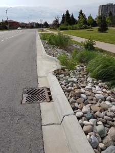
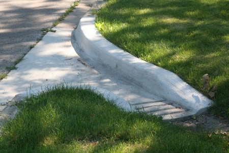
OPSD 605.040 Asphalt Spillway inlet to biofilter swale and road catch basin overflow outlet. County Court Blvd., Brampton, ON.
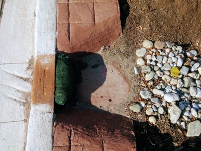
This curb cut has been sawn into existing concrete as part of a retrofit. Note the temporary (erosion log) and permanent stone erosion control measures in place. Mississauga Road, ON.
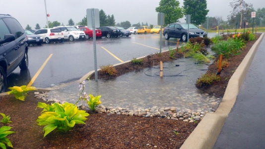
Curb cut used as a controlled overflow route from permeable pavements to a bioretention facility with monitoring well, Lake Simcoe Region Conservation Authority, Newmarket, ON.
Curb cut into a bioretention facility in Brown Deer, WI. Stone is used to reduce erosion around the inlet area. Photo credit: Aaron Volkening
Curb cut into a bioretention facility in Ajax, ON.
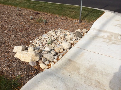
Stone lined inlet at IMAX site in Mississauga
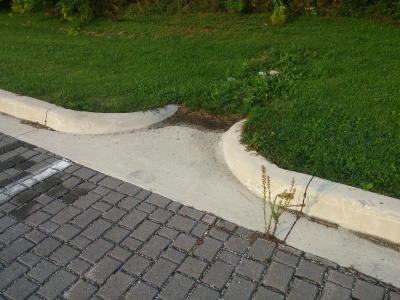
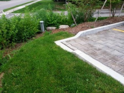
The grading around this inlet prevents flow in the correct direction. i.e. from the pavement onto the grass. Not too critical in this example, as the surface is permeable pavements.
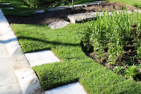
Curb cut into a rain garden on a green street in Newmarket, ON.
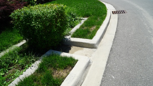
Curb cut leading into a small bioretention cell in Brampton, ON.
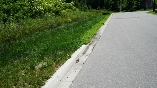
Curb cut leading to a bioswale in Brampton, ON.


For more information on curb cuts, see these pages: Curb cuts and Bioretention: Streetscapes
Pre-treatment and Inlet
Pre-treatment structures are most cost effective when they slow down incoming flows, collect sediment for easy clean out, and release water to the bioretention facility in a non-erosive way. Some pre-treatment structures/strategies include:
- Vegetation: If sized correctly, it works more effectively in areas with more dispersed flow. However, in concentrated flow and sediment areas it might not be the best option. Sediment removal can be more difficult in areas of dense vegetation. An advantage of using vegetation as pre-treatment is that it can be easily integrated into the landscape design.
- Concrete curbing
Construction steps:
Key Inspection Points:
- Verify that’s correct pretreatment device (jelly fish, vegetation, curbing, etc.)
- Correct size and location
- Correct elevation and footing
- Is it tied into the curb? Or could happen before the curbing?
- Does it work?
Mistakes to Avoid:
- Using wrong concrete forms if concrete curbs are selected
For more information about pre-treatment strategies and their design, visit these page: Pretreatment and Pretreatment features
Soil Media / Filter Media
Bioretention can be constructed over any soil type, but hydrologic soil group A and B are best for achieving water balance objectives. Facilities designed to infiltrate water should be located on portions of the site with the highest infiltration rates.
Construction Steps
For small LID facilities:
- Apply soil media in 150-300 mm lifts until desired top elevation of bioretention, bioswale or rain garden area is achieved
- Thoroughly wet each lift before adding the next and wait until water has drained through the soil before adding the next lift.
For large LID facilities:
- Apply soil media in 150-300 mm lifts with slinger trucks. This type of equipment will reduce the need to move soil media manually or by backhoe.
- Thoroughly wet each lift before adding the next and wait until water has drained through the soil before adding the next lift.
Key Inspection Points:
- When material arrives to the site: perform chain of custody, visual inspection and ribbon test to ensure that material meets design requirements.
- Ensure that soil media is being applied to the correct depth
Mistakes to Avoid:
- Machine compaction: Equipment should not be operated within the infiltration practice.
- Soil material: Accepting material that does not meet design specifications and requirements
- Soil material application: Applying the next lift without letting the previous lift of filter material dry.
- All exposed soil areas that are not being actively worked must have temporary erosion protection or permanent cover within 7 days for slopes 3:1 or greater and 14 days for slopes 3:1 or greater and 14 days for slopes 3:1 or flatter. This should apply to all exposed soil areas year-round and until the site is stabilized.
Finishing Grades: Inlet, Outlet, Biomedia, Plants (SPC)[edit]
Finish Grading
The finish grading process is another critical handoff moment as a number of elements such as curbs, sidewalks, soils and vegetation start to come together to create the functional and aesthetic value of a site. The same supervision and communication that was put into controlling ESC in earlier stages is also required during finish grading. In many cases, more attention to detail is needed for elements in this phase that will create or not the success of the final product.
Construction steps Soil Media:
- Backfill or sling material from outside of the LID facility at the lowest possible speed to avoid loss of component material.
- Apply material in 150-300 mm lifts until the desired elevation and thickness, allowing for positive flow.
- Wet material between lifts, allowing for drying before backfilling/slinging another lift
Key Inspection Points:
Mistakes to avoid:
Riprap (Large Stone)
Plant Material Verification and Installation
Mulch Placement
Stabilizing Contributing Drainage Area - Planting Adjacent Vegetation
Finishing Grades: Inlet, Outlet, Biomedia, Plants (JC)[edit]
As-built Survey
Throughout the construction process, it is sometimes necessary to deviate from the intended design of LID features and adapt the design to on-site conditions. The completion of a post-construction as-built survey is a standard operating procedure for engineering projects that captures and changes that were made to the feature’s design during construction.
Survey Steps:
- Use the same datum as the pre-engineering survey
- If a pre-engineering survey is not available, use a reference feature as the datum
- Include data on critical feature elevations and existing utilities, such as:
- Inverts of newly installed pipe
- Vertical and horizontal bends in pipes
- Existing public utilities
- Existing private utilities
- New and existing structures (e.g. catchbasins, manholes, chambers, etc.)
- Identify the type, diameter, and material of exposed utilities
Inspection Points:
- Datum matches the pre-engineering survey or selected reference feature
- Data provided in as-built survey matches the as-built standards of the City
Address Deficiencies and Assumption Protocols (JC)[edit]
Permanent Fencing
Delineating features with permanent fencing can eliminate tripping and falling hazards and protect soil media and plantings.
Construction Steps:
- Securely Install fencing around the perimeter of the feature
Inspection Points:
- Fencing size and material matches design
- Fencing is installed in correct location as per design
Identify and Address Deficiencies
Prior to passing responsibility to the landowner, contractors must ensure that any deficiencies in the LID feature’s construction are addressed. Keep in-mind what mistakes must be avoided during each construction task.
Assumption/Certification
Final inspection requirements are in-place to ensure that a final site-wide inspection is performed and allow for mitigation to occur before the contractor is relieved of responsibility. Final certifications are performed by knowledgeable personnel, such as the design engineer, who are qualified to ensure that LID features are operating as intended. This stage is critically important, as it is the last opportunity for issues to be resolved before the property owner assumes responsibility of the practice. The University of Minnesota and the Minnesota Pollution Control Agency recommend four (4) levels of inspection for final inspections of LID infiltration and filtration practices. The level of inspection, or combination of tests, that is selected is dependent on the goals of the assessment and feasibility of each inspection.
Visual Inspection (Level 1):
This qualitative method is low cost and requires minimal effort to conduct. Visual inspection should be used as an initial step to determine if the LID practice is operating properly. Visual inspections can be performed during dry weather and wet weather to identify situations where water is ponding for longer than intended (24 hours).
Surface Infiltration Capacity Testing (Level 2):
Using infiltrometers or permeameters to measure the hydraulic conductivity at several locations in the LID feature at various times of year can quantitatively verify that the practice can perform as intended.
Synthetic Runoff Testing (Level 3):
To perform the test, the practice must be filled with synthetic runoff and the change in water level must be monitored. Using clean water from a fire hydrant or water truck, synthetic runoff testing can measure the performance of an LID feature in a controlled environment. For this test to be feasible, a series of conditions must be met:
- A water supply that can deliver the required discharge and volume requirements
- The LID feature must be offline
- No precipitation must be expected for 48 hours
- Outflow paths must be temporarily plugged or measured (aside from infiltration)
- The water surface elevation can be measured throughout the test
Long-term Monitoring (Level 4):
Monitoring offers a comprehensive approach to assessing peak flow reduction and water volume reduction. These reductions can be quantified by completing a water budget during natural storm events, specifically through the measurement of inflow and outflow. Long-term monitoring is especially recommended if the LID feature that is the subject of the test is the first of its kind in its given jurisdiction, if geologic conditions pose a concern, or if the feature is being implemented to protect sensitive and significant natural features. It is important to recognize, however, that the unpredictability of natural storm events can lead to inaccuracies in data collection. Furthermore, long-term monitoring generally has the highest cost of the four levels of monitoring.