Inspection and Maintenance: Permeable Pavement
Overview[edit]
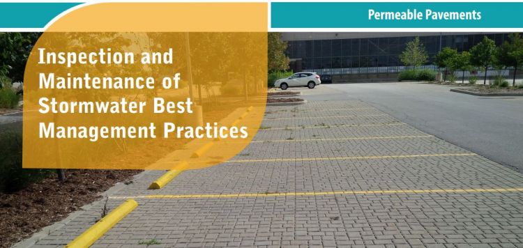
Permeable Pavement Permeable pavements contain many small openings (i.e., joints or pores) that allow rainfall and snowmelt (i.e., stormwater) to drain through them instead of running off the surface as it does on impervious pavements like conventional asphalt and concrete. An overflow outlet is needed to safely convey flows during flood events. Depending on the permeability of the underlying soil and other constraints, the pavement may be designed with no sub-drain for full infiltration, with a sub-drain for partial infiltration, or with an impermeable liner and sub-drain for a no infiltration practice. The sub-drain pipe may feature a flow restrictor (e.g., orifice cap or valve) for gradually releasing detained water and optimizing the amount drained by infiltration into the underlying soil.
Key components of Permeable pavements to pay close attention to are the:
Associated Practices[edit]
- Permeable Interlocking Pavers (i.e., Block Pavers) – Precast modular units made of concrete, pervious concrete or rubber/plastic composite designed to create open joints between pavers that are filled with fine, washed aggregate and installed on an open graded aggregate (i.e., clear stone) base and sub-base.
- Permeable Interlocking Grid Systems (i.e., grid pavers) – Precast concrete or manufactured plastic grids with open cells that can be filled with aggregate or a mixture of sand, gravel and topsoil and planted with grass or low-growing ground covers and are installed on an open-graded aggregate base.
- Pervious Concrete – a rigid pavement installed on an open-graded aggregate base that uses a cementitious binder to adhere aggregate together, similar to conventional concrete, except that the fine aggregate component is minimized or eliminated which results in the formation of connected pores throughout.
- Porous Asphalt – a flexible pavement installed on an open-graded aggregate base that uses a bituminous binder to adhere aggregate together, similar to conventional asphalt, except that the fine aggregate component is minimized or eliminated which results in the formation of connected pores throughout.
Inspection and Testing Framework[edit]

Component |
Indicators |
Construction Inspection |
Assumption Inspection |
Routine Operation Inspection |
Verification Inspection |
|---|---|---|---|---|---|
| Contributing Drainage Area | |||||
| CDA condition | x | x | x | x | |
| Perimeter | |||||
| BMP dimensions | x | x | x | ||
| Filter Bed | |||||
| Standing water | x | x | x | ||
| Trash | x | x | |||
| Vegetation | |||||
| Vegetation cover | x | x | x | x | |
| Vegetation condition | x | x | |||
| Vegetation composition | x | x | x | ||
| Underdrain & Monitoring Well | |||||
| Monitoring well condition | x | x | x | x | |
| Sub-drain/Perforated pipe obstruction | x | x | |||
| Outlets | Overflow outlet obstruction | x | x | x | x |
| Pavement Surface | Pavement surface condition | x | x | ||
| Pavement surface sediment accumulation | x | x | x | x | |
| Control structure condition | x | x | x | x | |
| Control structure sediment accumulation | x | x | x | x |

Component |
Indicators |
Construction Inspection |
Assumption Inspection |
Routine Operation Inspection |
Verification Inspection | |
|---|---|---|---|---|---|---|
| Testing Indicators | ||||||
| Surface infiltration rate testing | x | (x) | ||||
| Natural or simulated storm event testing | x | (x) | ||||
| Continuous monitoring | x | (x) | ||||
| Note: (x) denotes indicators to be used for Performance Verification inspections only (i.e., not for Maintenance Verification inspections) | ||||||
Construction Inspection Tasks[edit]

Construction inspections take place during several points in the construction sequence, specific to the type of LID BMP, but at a minimum should be done weekly and include the following:
- During site preparation, prior to BMP excavation and grading to ensure the CDA is stabilized and/or flow diversion devices are in place and confirm that construction materials meet design specifications
- At completion of excavation and grading, prior to backfilling and installation of pipes to ensure depths, slopes and elevations are acceptable
- At completion of installation of pipes, prior to completion of backfilling to ensure slopes and elevations are acceptable
- After final grading, prior to surface course installation to ensure depths, slopes and elevations are acceptable
- Prior to hand-off points in the construction sequence when the contractor responsible for the work changes (i.e., hand-offs between the storm sewer servicing, paving, building and landscaping contractors)
- After every large storm event (e.g., 15 mm rainfall depth or greater) to ensure flow diversion devices are functioning and adequately maintained. View the table below, which describes critical points during the construction sequence when inspections should be performed prior to proceeding further. You can also download and print the table here
Construction Sequence Step & Timing |
Inspection Item |
Observations* |
|---|---|---|
| Site Preparation - after site clearing and grading, prior to BMP excavation and grading | Natural heritage system and tree protection areas remain fenced off | |
| ESCs protecting BMP layout area are installed properly | ||
| CDA is stabilized or runoff is diverted around BMP layout area | ||
| BMP layout area has been cleared and is staked/delineated | ||
| Benchmark elevation(s) are established nearby | ||
| Construction materials have been confirmed to meet design specifications | ||
| BMP Excavation and Grading - prior to backfilling and installation of pipes/catchbasins | Excavated soil is stockpiled outside the CDA | |
| Excavation location, footprint, depth and slope are acceptable | ||
| BMP Installation – after installation of pipes/catchbasins, prior to completion of backfilling | Structural components (e.g., pavement base, curbs) installation is acceptable | |
| Impermeable liner installed correctly, if applicable | ||
| Installations of sub-drain pipes (e.g., locations, elevations, slopes), standpipes/monitoring wells are acceptable | ||
| Sub-drain trench dams installed correctly (location, elevation) | ||
| Surface coarse installation (elevation, slope, monitoring wells) is acceptable |
Routine Maintenance - Key Components and I&M Tasks[edit]
Regular inspections (twice annually, at a minimum) done as part of routine maintenance tasks over the operating phase of the BMP life cycle to determine if maintenance task frequencies are adequate and determine when rehabilitation or further investigations into BMP function are warranted.
Table below describes routine maintenance tasks for bioretention practices, organized by BMP component, along with recommended minimum frequencies. It also suggests higher frequencies for certain tasks that may be warranted for BMPs located in highly visible locations or those receiving flow from high traffic areas (vehicle or pedestrian). Tasks involving removal of trash, debris and sediment and weeding/trimming of vegetation for BMPs in such contexts may need to be done more frequently (i.e., higher standards may be warranted).
Individuals conducting vegetation maintenance and in particular, weeding (i.e., removal of undesirable vegetation), should be familiar with the species of plants specified in the planting plan and experienced in plant identification and methods of removing/controlling noxious weeds. Key resources on these topics are provided below at the links provided:
- Agriculture and Agri-food Canada’s Weed Info database
- Ontario Ministry of Agriculture, Food and Rural Affairs’ Ontario Weed Gallery
- Ontario Ministry of Agriculture, Food and Rural Affairs’ Noxious Weeds In Ontario list
- Ontario Invasive Plant Council’s Quick Reference Guide to Invasive Plant Species
- Oregon State University Stormwater Solutions, 2013, Field Guide: Maintaining Rain Gardens, Swales and Stormwater Planters, Corvallis, OR.
- Plants of Southern Ontario (book), 2014, by Richard Dickinson and France Royer, Lone Pine Publishing, 528 pgs.
- Weeds of North America (book), 2014, by Richard Dickinson and France Royer, University of Chicago Press, 656 pgs.
| Comnponent | Description | Inspection & Maintenance Tasks | (Pass) Photo Example | (Fail) Photo Example |
|---|---|---|---|---|
| Contributing Drainage Area (CDA) |
Area(s) from which runoff directed to the BMP originates; includes both impervious and pervious areas. |
|
||
| Pretreatment |
Devices or features that retain trash, debris and sediment; help to extend the operating life cycle; examples are eavestrough screens, catch basin inserts and sumps, oil and grit separators, geotextile-lined inlets, gravel trenches, grass filter strips and forebays. |
|
 Forebay is free of sediment, trash and debris and recently maintained. The large stones in the feature are used to slow down and spread out inflowing water into the feature and they remain well arranged and in place. |
 An erosion gully occurring where bare soil is starting to become visible on the grass filter strip pretreatment feature at the inlet, thus indicating it is not effectively slowing and spreading out the inflow of stormwater to the BMP. |
| Inlets |
Structures that deliver water to the BMP (e.g., Curb cuts, spillways, pavement edges, catch basins, pipes). |
|
||
| Perimeter |
Side slopes or structures that define the BMP footprint; may be covered by a mixture of vegetation, mulch and stone with slopes up to 2:1 (H:V), or concrete or masonry structures with vertical walls. |
|
||
| Filter Bed |
Flat or gently sloping area composed of a 0.5 to 1 m deep layer of filter media soil covered by a mixture of vegetation, mulch and stone where surface ponding and filtration of runoff occurs. |
|
||
| Vegetation |
A mixture of deep rooting perennial plants, tolerant to both wet and dry conditions and salt (if receiving pavement runoff); can include grasses, flowers, shrubs and trees; roots uptake water and return it to the atmosphere; provide habitat for organisms that break down trapped pollutants and help maintain soil structure and permeability. |
|
||
| Overflow Outlet |
Structures that convey overflows to another BMP or municipal storm sewer. |
|
||
| Sub-drain |
Optional component; perforated pipe(s) surrounded by gravel and may be wrapped in geotextile filter fabric; installed below the filter media soil layer to collect and convey treated water to an adjacent drainage system; may also include a flow restrictor. |
|
||
| Monitoring well |
Perforated standpipe that extends from the bottom of the BMP to above the invert of the overflow outlet. Allows measurement of subsurface water level to track drainage performance over time. |
|


- ↑ TRCA. 2016. Fact Sheet - Inspection and Maintenance of Stormwater Best Management Practices: Permeable Pavement. https://sustainabletechnologies.ca/app/uploads/2018/02/Permeable-Pavement-Fact-Sheet.pdf
- ↑ STEP. 2018. Fact Sheet - Inspection and Maintenance of Stormwater Best Management Practices: Permeable Pavements. https://sustainabletechnologies.ca/app/uploads/2018/02/Permeable-Pavement-Fact-Sheet.pdf