Stormwater planters
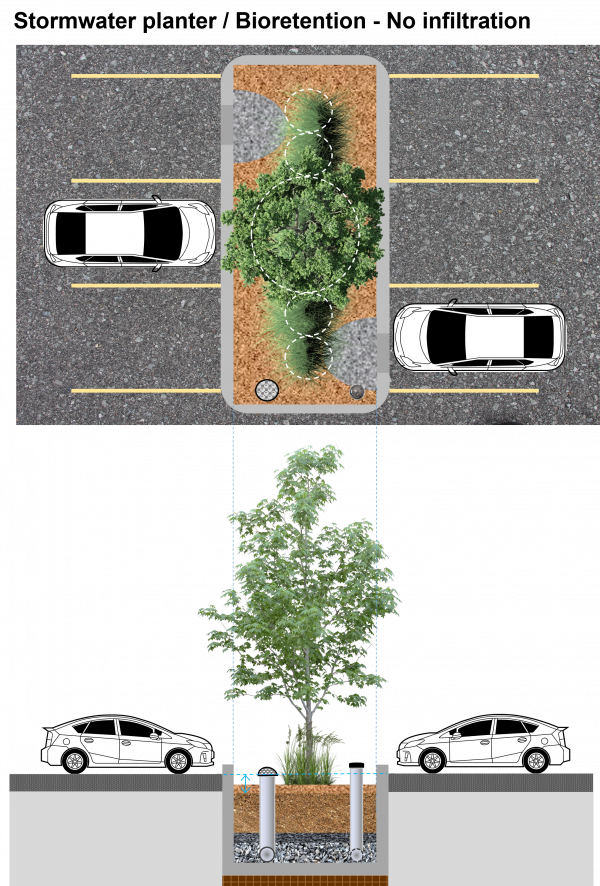

Over underground infrastructure, soils prone to subsidence, or on sites considered to be pollution hot spots, it may be necessary to prevent all infiltration. Stormwater planters are "no infiltration" or "filtration-only" BMPs, similar to bioretention cells, that can be squeezed into tight urban spaces, adjacent to buildings and within the usual setbacks required for infiltrating facilities. Stormwater planters can also be used as a means of providing building-integrated LID by capturing a portion of the rainwater from the rooftop. This type of cell can be constructed above grade in any waterproof and structurally sound container, e.g. in cast concrete or a metal tank.
Overview[edit]
Stormwater planters are an ideal technology for:
- Sites which cannot infiltrate water owing to contaminated soils or shallow bedrock,
- Zero-lot-line developments such as condos or dense urban infill.
Take a look at the downloadable Bioretention Factsheet below for a .pdf overview of this LID Best Management Practice:

The fundamental components of a stormwater planter are:
- a planting bed of filter media,
- suitable vegetation,
- decorative aggregate or stone,
- An underdrain,
- An impermeable liner
The design may benefit from:
Planning Considerations[edit]
Stormwater planters may be integrated into the landscape similarly to bioretention practices. See bioretention planning.
Additional site opportunities[edit]
As they do not require connection to the earth for infiltration purposes, stormwater planters can also be used in elevated locations. They are sometimes used in retrofit applications on otherwise impermeable surface, as raised beds or planters surrounding buildings. They can be employed to capture runoff from roof drains or downspouts or even upon terraces or vertical surfaces of buildings.
Design[edit]

This article is specific to flow-through stormwater planters, vegetated systems that do not infiltrate water to the native soil.
If you are designing a planted system which does infiltrate water, see advice on Bioretention: Sizing.
The dimensions of a stormwater planter are largely predetermined according to the function of the component. As they do not contain a storage reservoir the planters rely more upon careful selection of materials. Both the filter media and the perforations of the pipe play critical roles for flow control.
| Component | Recommended depth (with underdrain pipe) | Typical porosity (n) |
|---|---|---|
| Ponding (dp) | 150 to 450 mm | 1 |
| Mulch | 75 ± 25 mm |
|
| Filter media (dm) |
|
|
| Pipe diameter reservoir | Is equal to underdrain pipe diameter | 0.4 |
| Pipe bedding (db) | 50 mm (although commonly omitted altogether). | 0.4 |
Filter media[edit]
See Bioretention: Filter media
Underdrain[edit]
Stormwater planters differ from full and/or partial infiltration bioretention practices in that the storage function is provided only by the water retention capacity of the filter media. As such, there is no storage reservoir and the only purpose to the aggregate layer is to drain water to the perforated pipe. For this, a medium aggregate as described in choker layer is recommended as it negates the need for a separating layer to the filter media. Design details can be found here Underdrains for non-exfiltrationg practices.
Planting[edit]
- Planters must be designed in a way that insulates the soil through freezing temperatures, or plant species that can survive the winter season in raised planters must be used.
- Stormwater planters routinely capture only rainwater flowing from adjacent rooftops. This means that salt may be less of a concern than in Bioretention: Parking lots or Bioretention: Streetscapes.
- The plant lists are still a good place to start when selecting species for LID in Ontario.
- A more formal aesthetic for the planting design is appropriate for the urban hardscape setting.
Error: Image is invalid or non-existent.
Over underground infrastructure, soils prone to subsidence, or on sites considered to be pollution hot spots, it may be necessary to prevent all infiltration. Stormwater planters are "filtration-only" BMPs, similar to bioretention cells, that can be squeezed into tight urban spaces, adjacent to buildings and within the usual setbacks required for infiltrating facilities. Stormwater planters can also be used as a means of providing building-integrated LID by capturing a portion of the rainwater from the rooftop.
This type of cell can be constructed above grade in any waterproof and structurally sound container, e.g. in cast concrete or a metal tank.
Liners[edit]
An impermeable liner is incorporated into non-infiltrating practices such as stormwater planters, and may be applied in permeable pavements installations where separation from the native soils and groundwater is required.
- Waterproof containment can be created using concrete or a plastic membrane/liner (HDPE or EPDM are common materials).
- When the membrane is being used directly in the ground, punctures from stones can be prevented by compacting a layer sand (30 - 50 mm) over the soil prior to installing the membrane.
- Alternatively, a manufactured cushion fabric (geotextile) can be employed for this purpose.
- The top surface of the membrane must also be protected from stone and gravel being used for inside the BMP. Again, sand or a cushion fabric may be used.
- When a pipe is used to provide drainage from the practice to an outlet structure or storm sewer, a 'pipe boot' or flange should be sealed to both the pipe and the liner to prevent leaks.
Filter bed surface[edit]
As stormwater planters are often quite small and receive very rapid flow, both a level spreader and the use of mulch and stone to dissipate energy from concentrated inflow are strongly recommended.
Gallery[edit]
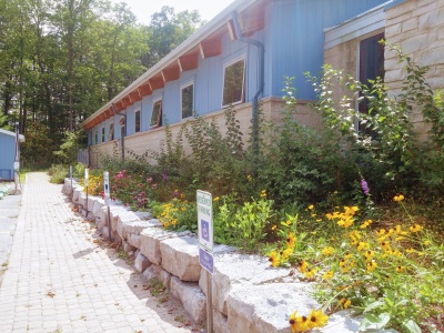
Stormwater planters are ideal for situating alongside buildings to capture rainwater from roof runoff. LSRCA headquarters, 2017.
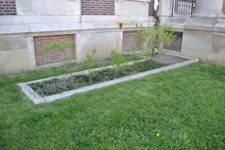
Stormwater planter, treating downspout runoff, at Waterview Rec Center, Philidelphia
Photo credit: PWD
Rain garden, Illick Hall, SUNY College of Environmental Science and Forestry, Syracuse, NY
Photo credit: DASonnenfeld


Performance[edit]
Hydrology[edit]
Water quality[edit]
See Also[edit]
Proprietary links[edit]
A number of precast modules exist to contain treatment media. As many of these systems are enclosed water balance calculations may be erroneous where evapotranspiration is constrained.
In our effort to make this guide as functional as possible, we have decided to include proprietary systems and links to manufacturers websites.
Inclusion of such links does not constitute endorsement by the Sustainable Technologies Evaluation Program.
Lists are ordered alphabetically; link updates are welcomed using the form below.
- ↑ Davis, Allen P., Robert G. Traver, William F. Hunt, Ryan Lee, Robert A. Brown, and Jennifer M. Olszewski. “Hydrologic Performance of Bioretention Storm-Water Control Measures.” Journal of Hydrologic Engineering 17, no. 5 (May 2012): 604–14. doi:10.1061/(ASCE)HE.1943-5584.0000467.
- ↑ Yeakley, J.A., and K.K. Norton. “Performance Assessment of Three Types of Rainwater Detention Structures for an Urban Development in Wilsonville, Oregon, USA,” 70. Portland, 2009.
- ↑ Macnamara, J.; Derry, C. Pollution Removal Performance of Laboratory Simulations of Sydney’s Street Stormwater Biofilters. Water 2017, 9, 907.;doi:10.3390/w9110907
- ↑ Lucke, T., & Nichols, P. W. B. (2015). The pollution removal and stormwater reduction performance of street-side bioretention basins after ten years in operation. Science of The Total Environment, 536, 784–792. https://doi.org/10.1016/J.SCITOTENV.2015.07.142
- ↑ Macnamara, J.; Derry, C. Pollution Removal Performance of Laboratory Simulations of Sydney’s Street Stormwater Biofilters. Water 2017, 9, 907. doi:10.3390/w9110907