Dry ponds
See also Water squares
Also known as infiltration basins or detention basins (according to their features). Dry ponds are a grassed alternative to bioretention cells. This permits the landscape to be accessed and used as an amenity space.
Overview[edit]
Dry ponds are recommended as flood control structures to accommodate occasional excess overflow downstream of other structural BMPs. They should be integrated into the landscape as useful, accessible public space.
Dry ponds are ideal for:
- Managing infrequent extreme flow events,
- incorporating into parks and other green recreational spaces,
- distributing across a larger development site
Planning considerations[edit]
Dry ponds are a useful tool for managing flooding during larger storm events. They are well suited to being placed downstream of other smaller distributed BMPs for occasional backup flood protection. Where possible they should be integrated into amenity space, given that users rarely wish to continue outdoor activities during such intense rainstorms.
Compared to wet ponds “Dry ponds… …are less expensive to install, require less maintenance and may involve less liability for the communities around them.” https://www.fairfaxcounty.gov/soil-water-conservation/understanding-stormwater-ponds
Risk[edit]
Where temporary storage of water occurs on the surface the depth and rate of rise of the water should be sufficiently low that risks posed by the water body are minimized for site users (taking into account the temporary nature of the storage facility which will mean that the public are not accustomed to its presence). A risk assessment should be undertaken of the frequency and rate of flooding to a range of inundation depths in order that public safety is not jeopardised. [2]
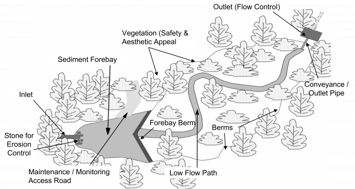
Design[edit]
| Element | Design Objective | Criteria |
|---|---|---|
| Drainage Area | Minimum orifice size (see flow control) | 5 Ha (≥10 Ha preferred) |
| Treatment Volume | Provision of appropriate level of protection | See below |
| Active Storage | Detention | Suspended solids settling 24 hrs (48 hrs preferred) |
| Forebay | Pre-treatment |
|
| Length-to-Width Ratio | Maximize flow path and minimize short-circuiting potential |
|
| Depth | Safety | Maximum 3 m |
| Side slopes (See also berms) | Safety |
|
| Inlet | Avoid clogging/freezing |
|
| Outlet (See also flow control) | Avoid clogging/freezing |
|
| Maintenance access | Access for backhoes or dredging equipment |
|
| Buffer | Safety | Minimum 3 m above maximum water quality/erosion control water level |
The bottom of a dry pond should be flat to encourage uniform ponding and infiltration across the entire surface. Recommended tolerance on base levels 10 mm in 3m.
The side slopes should be no steeper than 1:3 to permit vegetation stabilization and access for maintenance and amenity. This may be relaxed where the pond area is very shallow (0.5 m). stepped or benched slopes are also a possibility, but consideration should be made of maintenance access. [2]
Volume[edit]
The surface storage volume of a dry pond (Ap) is determined:

Where:
- RVCT = Runoff volume control target (mm)
- Ac = Area of the catchment (m2)
- f' = design infiltration rate (mm/hr)
- t = time permitted for ponding to infiltrate (hrs) (typically 48 hours)
Outlet[edit]
Detention time[edit]
A detention time of 24 hours should be targeted in all instances. Where this necessaitates a very low outflow, a vortex valve or similar is recommended over an orifice or pipe restiction. The detention time is approximated by the drawdown time. The drawdown time in the pond can be estimated using the classic falling head orifice equation which assumes a constant pond surface area[3]. This assumption is generally not valid, and a more accurate estimation can be made if the equation is solved as a differential equation. This is easily done if the relationship between pond surface area and pond depth is approximated using a linear regression:

Where
- t = Drawdown time (s)
- Ap = Surface area of the pond(m2)
- C = Discharge coefficient (typically 0.63)
- Ao = Cross-sectional area of the orifice(m2)
- g = Gravitational acceleration constant (9.81 m/s2)
- h1 = Starting water elevation above the orifice (m)
- h2 = Ending water elevation above the orifice (m)
C2 slope coefficient from the area-depth linear regression C3 intercept from the area-depth linear regression
Excess flow control[edit]
- https://www.fhwa.dot.gov/engineering/hydraulics/software/hy8/
- https://www.hydrologystudio.com/no-fail-detention-pond-design/
Modeling[edit]


![]()
| Stage Storage | |
|---|---|
| Name | Important to have a unique name, to connect it with the catchment area |
| Storage type | Dry detention ponds |
| Bottom elevation (m) | This is important to correspond with other components, e.g. when the overflow is coupled to another BMP within a treatment train |
| Maximum depth (m) | |
| Lined/unlined | Unlined (ideally) |
| Underlying soil | Choose from five; sandy soils drain more quickly. |
| Evaporation factor | ? |
| Suction head (mm) | ? |
| Saturated conductivity (mm/hr) | ? |
| Initial soil moisture deficit (fraction) | ? |
| Curves | |
| The Curves table is designed to accommodate the side slopes. The top line begins at 0 m, with subsequent depths in the following lines. | |
Materials[edit]
Resilient turf grasses are particularly useful in the design of vegetated filter strips, dry ponds and enhanced grass swales. The Ministry of Transportation have standardized a number of grass mixes[4]. The 'Salt Tolerant Mix' is of particular value for low impact development applications alongside asphalt roadways and paved walkways.
| Common name | Scientific name | Proportion |
|---|---|---|
| Tall Fescue | Festuca arundinacea | 25 % |
| Fults Alkali Grass | Puccinellia distans | 20 % |
| Creeping Red Fescue | Festuca rubra | 25 % |
| Perennial ryegrass | Lolium perrenne | 20 % |
| Hard Fescue | Festuca trachyphylla | 10 % |
Gallery[edit]
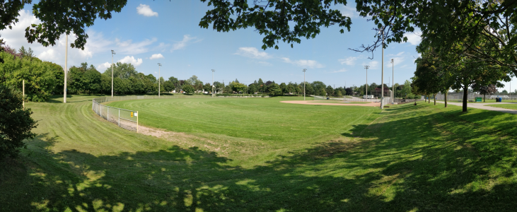
Wishing well park is a baseball field with flood warning signs, Scarborough ON
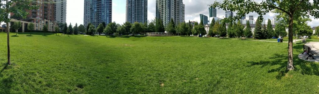
Avondale Park, designed for flood storage, but not optimized for infiltration, North York ON
A multi-functional dry basin, still due to be fitted with playground equipment. Cambridge, UK. Photo credit: Simon Bunn

Stormwater lagoon, Wilmhurst Road, Warwick. UK. Photo credit: Robin Stott

Dry polder northwest of Vincencov, Prostějov. Czech Republic. Photo credit: Jiří Komárek


External links[edit]
To review[edit]
https://www.google.com/imgres?imgurl=http%3A%2F%2Fwww.calgary.ca%2FUEP%2FWater%2FPublishingImages%2FBraeside-Dry-Pond-610px.jpg&imgrefurl=http%3A%2F%2Fwww.calgary.ca%2FWWCDI&docid=RBtJ2qx0jhourM&tbnid=-OUrotj9LMYmfM%3A&vet=10ahUKEwjpwbyNt-bfAhXlguAKHS1pDtQQMwhjKBcwFw..i&w=610&h=299&bih=723&biw=1536&q=traplow%20stormwater&ved=0ahUKEwjpwbyNt-bfAhXlguAKHS1pDtQQMwhjKBcwFw&iact=mrc&uact=8 https://www.fairfaxcounty.gov/publicworks/sites/publicworks/files/assets/documents/drypond_1.pdf
- ↑ Ministry of the Environment. Stormwater Management Planning and Design Manual. https://dr6j45jk9xcmk.cloudfront.net/documents/1757/195-stormwater-planning-and-design-en.pdf. 2003. Accessed 3 September, 2021
- ↑ Jump up to: 2.0 2.1 Ballard, B. W., Wilson, S., Udale-Clarke, H., Illman, S., Scott, T., Ashley, R., & Kellagher, R. (2015). The SuDS Manual. London.
- ↑ Jump up to: 3.0 3.1 Ontario Ministry of Environment. (2003). Stormwater Management Planning and Design Manual. Retrieved January 15, 2017, from https://www.ontario.ca/document/stormwater-management-planning-and-design-manual/stormwater-management-plan-and-swmp-design
- ↑ Ontario Provincial Standard Specification. (2014). Construction Specification and for Seed and Cover OPSS.PROV 804. Retrieved from http://www.raqsb.mto.gov.on.ca/techpubs/ops.nsf/0/3a785d2f480f9349852580820062910a/$FILE/OPSS.PROV 804 Nov2014.pdf