Smart Blue Roof - Project Overview
The sections below are intended to mirror the information provided in the Smart Blue Roof Tour hosted at CVC’s Head Office or serve as a review of the material presented during the tour.
Click here for a summarized overview.
Introduction[edit]
Conventional flat roofs on industrial, commercial, and institutional buildings are designed to quickly remove rainwater from their surfaces. The passive control strategy of these conventional roof assemblies provides no opportunity for rainwater reuse and contributes to downstream erosion and the potential for flooding. Credit Valley Conservation’s Smart Blue Roof (SBR) flips this idea on its head and uses an active control strategy to capture rainwater for reuse. This emerging technology has the capacity to effectively manage runoff, capture rainwater for non-potable reuse, and conserve energy through evaporative cooling. What makes the SBR cutting-edge is that it is the first blue roof system to be compliant with the Canadian Standards Association’s new Rainwater Harvesting Standard (CSA B805-18). Compliance with this standard is essential, because it is anticipated to be incorporated into the Ontario Building Code (OBC) in the near future. The key objective of this pilot project is to explore the potential of this new technology and pave the way for others to adopt active stormwater controls.
Station 1 – Roof Surface[edit]
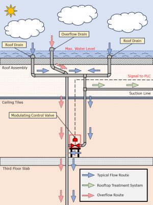
By utilizing the roof of Building A for storage, CVC’s head office gains the ability to capture an additional 40,000 L of rainwater. A structural load assessment conducted by WSP Canada concluded that an average depth of 130 mm of rainwater could safely be supported by Building A’s roof assembly. Since Building A’s roof is gently sloping, this corresponds to a depth of 75 mm at the parapet (roof edge) and 250 mm at the roof drains (lowest point). Rainwater can be held on the roof for up to six (6) days. Whether rainwater is retained on the building’s roof or drained into the basement for treatment is determined by the modulating control valves on the building’s third floor.
The roof membrane installed on the SBR is a polymethyl methacrylate (PMMA) membrane, which was liquid-applied and rolled on like paint. Because of this, the membrane has no seams that could lend themselves to leaks on the roof. The SBR has four (4) roof drains and two (2) overflow pipes that direct rainwater to the basement cistern. The roof surface also has an electric field vector mapping (EFVM®) leak detection system and two (2) redundant overflow scuppers that can direct rainwater to the foot of the building in the extremely unlikely event that both overflow pipes fail. The SBR is not expected to overflow for over 100 years…
Station 2 – Modulating Control Valves[edit]
The key mechanisms for the SBR’s ability to hold water are the modulating control valves installed on the third floor. Whereas typical flat roof buildings allow rainwater to passively drain from their roofs without rainwater retention, the SBR roof drains are configured with valves that stop drainage from occurring. These valves allow water to pond on the roof up to a safe maximum depth, determined by the height of the overflow pipes, which is an average of 130 mm in the case of the SBR. Water that is held back by these valves is passed through the SBR’s first CSA-compliant treatment system via a suction line that is installed immediately upstream of the east modulating control valve.
Station 3 – Third-Floor Treatment System[edit]
The OBC requires that flat roofs do not allow rainwater to pond beyond a maximum depth 150 mm. Furthermore, the OBC demands that rainwater is drained within 24 hours. In order to maximize the benefits of rainwater capture, CVC sought exemptions from these restrictive clauses of the OBC. The City of Mississauga granted both of these exemptions, under a set of conditions.
To demonstrate that the roof could safely support more than a maximum of 150 mm of water, a structural load assessment was conducted by WSP Canada. This assessment concluded that ponding an average of 130 mm across CVC’s sloped roof applied a very similar force and torque distribution profile as ponding 130 mm across a completely flat roof. As such, it was considered safe to pond water at a depth of 75 mm at the parapet (roof edge) and 250 mm at the roof drains (lowest point) by the City of Mississauga, and an exemption was granted.
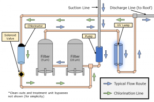
The OBC specifies a maximum rooftop retention time of 24 hours because standing water can lead to the proliferation of algae, bacteria, and mosquitoes. To avoid the rise of water quality issues, the City of Mississauga required that CVC install a separate CSA-compliant water recirculation system on the third floor. This system draws rooftop rainwater through the recirculation line that is immediately upstream of the east modulating control valve. The following are the main treatment components found on the third floor:
- Micron Filters: Remove any fine debris from the rainwater. This filtration is important for removing impurities, eliminating odours, and ensuring debris does not impede the efficacy of the ultra-violet (UV) treatment unit by blocking light. Two (2) filters are present, the first with a filter pore size of 20 μm and the second with a filter pore size of 5 μm – A pore size of 5 μm is required for CSA compliance.
- UV Lamp: Disinfects rainwater by sterilizing bacteria and viruses with UV radiation. Note that UV disinfection does not have any residual effect that can be harmful to humans or aquatic life. A dosage of 40 mJ/cm^2 is administered – This dosage is required for CSA-compliance.
- Chlorine Pump: Provides a chlorine residual of 0.5 mg/L that can ensure that rainwater on the roof surface is protected from recontamination.
- Solenoid Valve: Determines when chlorination is allowed to occur by opening when the rooftop chlorine residual is too low.
It is important to note that chlorination only occurs when the roof water’s chlorine residual drops below 0.5 mg/L, at which water is passed through a chlorination unit and directed back to the filters. This recirculation system was not included in the original SBR design, but its inclusion will ensure that the ponding of water on the roof does not present any water quality and human health concerns.
Station 4 – Basement Cistern and Treatment System[edit]
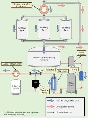
When rainwater is drained from the roof surface into the basement, it is collected by a rainwater cistern (CVC’s old, passive system). Water from this cistern can be pumped through the SBR’s second CSA-compliant treatment system. The following are the main treatment components of this basement system:
- Settling Tanks: Allow any sediment that is suspended in the rainwater drained from the roof to settle out before rainwater enters the cistern. Three (3) settling tanks are present.
- Rainwater Cistern: Has capacity for up to 5,000 L of rainwater. This cistern holds water that will then be pumped through the CSA-compliant treatment system. After treatment, rainwater is used in Building A’s toilets.
- Micron Filter: Removes any fine debris from the rainwater that was not settled out in the settling tanks. This filtration is important for removing impurities, eliminating odours, and ensuring debris does not impede the efficacy of the UV treatment unit by blocking light. Filter pore sizes of 100 μm and 5 μm are used.
- UV Lamp: Disinfects rainwater by sterilizing bacteria and viruses with UV radiation. Note that UV disinfection does not have any residual effect that can be harmful to humans or aquatic life. A dosage of 40 mJ/cm^2 is administered.
- Chlorine Pump: Provides a chlorine residual of 0.5 mg/L that can ensure that rainwater is protected from recontamination in the distribution line or when supplied to the toilets. Chlorination is not required for CSA compliance, but it was added for good measure.
- Agitator: Mixes the newly introduced chlorine solution into the treated rainwater. This ensures that water is sufficiently mixed prior to being added to the greywater line.
Once treatment is complete, the rainwater is added to Building A’s greywater line for use in the building’s toilets. Currently, rainwater is only planned for use in toilets, but greywater use could be expanded to irrigation applications at a later phase. Although CVC would have no need for it, there is potential for rainwater to be reused for industrial uses, like vehicle washing and industrial processes. Upgrading the treatment systems could also make rainwater reusable as potable water.
Station 5 – Programmable Logic Controller[edit]
The SBR is an active stormwater control because it utilizes control logic to make decisions on how captured rainwater is best utilized. The SBR is equipped with a series of sensors and a central programmable logic controller (PLC). The PLC is fed information from the sensors, and these data streams are used by the PLC to decide how the system should be manipulated to maximize the benefits of the SBR. Here are some of the key sensors that are part of the SBR’s operation:
- Electromagnetic Flowmeter: Measures amount of rainwater that is conveyed into the basement. This measures how much water is being drained from the SBR and how much water is harvested OR overflows into the storm sewer (if the cistern overflows).
- Greywater Flowmeter: Measures the amount of treated water that is introduced into the greywater line.
- Rooftop Level Sensor: Measures elevation of rainwater on the roof. This is useful for determining if there is enough water on the roof to fill up the basement cistern without jeopardizing the ability of the third-floor treatment system to recirculate water.
- Cistern Level Sensor: Measures elevation of rainwater in the cistern. This is useful for determining if the cistern needs to be replenished.
- Rooftop temperature Sensors: Measures the temperatures above the building and on the inside of the roof assembly (below the concrete roof slab). These sensors compare the heat gradient across the roof assembly where the SBR is located and where a conventional roof system remains. By doing so, the cooling benefit and energy savings of the SBR can be calculated.
The data collected from these sensors is used to optimize rainwater use and quantify the SBR’s performance. An example of a possible optimization scenario is the decision to prioritize treatment and distribution or the evaporative cooling benefits of the SBR based on atmospheric temperature. This decision is based on the atmospheric temperature outside of Building A. These are the details of the two (2) temperature scenarios:
- External Temperature Below 20°C: Priority is placed on ensuring the cistern is filled with enough rainwater to supply toilets. Roof surface readily drains roof water to the basement.
- External Temperature Above 20°C: Priority is placed on maximizing evaporative cooling benefits. Rainwater depth on the roof is maximized and rainwater is not drained to the basement cistern. If the basement cistern is empty, municipal water is used in the toilets.
Data is transmitted to the PLC from the various sensors, and these data streams are uploaded to CVC’s existing WISKI database to calculate key performance indicators (KPI’s). Some of the KPI’s for the SBR include the following:
- Volume of Water on the Roof: Determined using the level sensor installed on the SBR surface and the mathematical “stage-storage” relationship (based on the roof’s geometry) between water depth and water volume.
- Daily Water Volume Evaporated: Determined by calculating how much captured rainwater does not make it through the basement electromagnetic flowmeter.
- Total Volume of Stormwater Managed: Calculated as the amount of rainwater that is supplied to toilets or evaporated. Managed stormwater does not have the opportunity to contribute to flooding or erosion.
- Net Energy Savings: The sum of energy savings through evaporative cooling and energy savings from avoiding the need to treat and distribute water from Lake Ontario for use in Building A. This amount considers the energy demands of the in-house treatment systems.
- Emissions Prevented by Reduced Potable Water Demand: Greenhouse gas emission reductions due to a lowered need for electricity in the Region of Peel’s water treatment system.
These KPI’s, and others, will be important metrics for quantifying the benefits of CVC’s SBR. With the information gained from this implementation study, the potential of this emerging technology can be understood by others. Through knowledge dissemination, CVC aims to showcase SBR technology as an effective and feasible stormwater management and water conservation solution.


