Trench, chamber, and perforated pipe: Installation
The guidance provided in this section is applicable for the construction of soakaway pits, infiltration chambers, infiltration trenches, and exfiltration pipes of varying size and shape, since the installation of each of these features is similar. The StormTech Installation Guide[1] is a key resource for understanding the construction of these features.

- Apply clear stone to the floor of the excavation to act as the base for chambers, pipes, and trenches.
- For infiltration chamber construction, install chamber feeder-pipes to the top of the base, connecting to the inlet control manhole, where applicable.
- Roll out scour fabric length-wise beside any feeder-pipes that have been installed, if specified in the design.
- If specified, lay out scour fabric where the base of the infiltration chamber, soakaway, or pipe is anticipated to be installed. No seams should be present where the fabric underlies chambers.
- Install chambers, trenches, or perforated pipes at the location and elevation specified in the contract documents. Where infiltration chambers need to be assembled from units, install each piece of the chamber row, as per the manufacturer’s instructions, until the entire length of the chamber is in place. The ends of the chamber may be installed just prior to perimeter stone being applied to the ends of the rows, if desired, to ensure ease of inspection.
- Connect any perforated pipe connections, underdrains, roof leaders, or observation wells at the appropriate elevations, per the design.
- With a stone conveyor or excavator, begin placing clear stone as specified in the design. For domed chambers, place stone along the centreline of the chamber rows. Doing so will distribute stone to either side of the chamber, anchoring each side in roughly equal proportion.
- Backfill the excavated area with clear stone to the depth specified in the contract documents. Ensure that the depth of stone does not differ by more than 300 mm between the sides of any given chamber row at any point during the backfilling process.
- Once backfilling is complete, level the perimeter stone with a small dozer. Only push material in the direction parallel to the rows.
- If specified by the design, roll geotextile parallel to rows over the top of stone. Provide sufficient overlap, as specified by the manufacturer.
Note: where many rows of infiltration chambers are being installed, it may be advisable to construct the chamber rows piece-wise as the application of perimeter stone progresses to provide space for excavators to apply the stone from on top of the stone base. See the adjacent photo for an example.
Key Inspection Points:
- Feeder-pipes protrude into the storm chambers at the appropriate length, per manufacturer’s specifications.
- Scour fabric does not overlap beneath the walls of open-bottom chambers.
- Minimum distance between adjacent chambers is provided.
- Minimum depth of stone below and stone above chamber is provided, per manufacturer specifications.
- Depth of chamber inverts are installed correctly, relative to the elevation of the inlet, such that the storage potential of chambers are maximized.
- Infiltration chambers are assembled as specified by the manufacturer.
- Perimeter stone extends to the excavation walls.
- LID practice is protected with applicable ESC to avoid contamination of infiltration area or materials.
Mistakes to Avoid:
- Equipment on the perimeter stone: Perimeter stone should be applied with a stone conveyor or excavator from the outside of the LID footprint or on the stone foundation.
- Uneven perimeter stone: Perimeter stone must be applied such that the depth of stone on one side of the chamber is not unacceptably higher than the other. Refer to design details.
- Incorrect inlet elevation: For applications where infiltration chambers overflow into a sewer, it is important that the top of chamber is positioned at an elevation below the lowest invert of the other sewer connections. Otherwise, only part of the chamber volume can be utilized.
- Damaged or missing ESC: Ensure that ESC protection is adequately inspected
- Putting system online prematurely: Do not allow the feature to receive stormwater when contributing drainage area is not stabilized and sediment and debris is present.
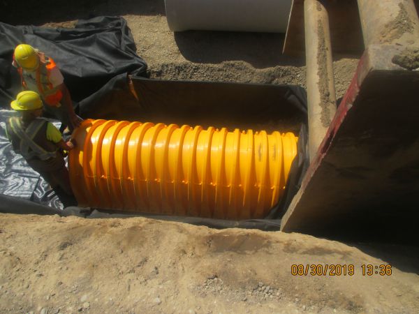
Chamber resting on top of scour fabric at Alton Main Street. (Photo Source: CVC, 2019)
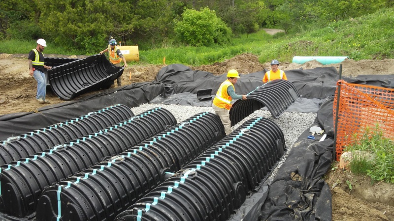
Components of an infiltration chamber being overlapped. (Photo Source: CVC, n.d.)
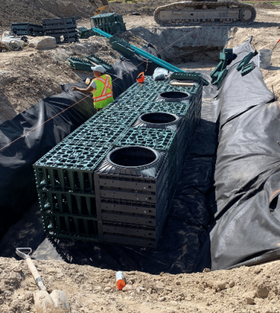
Example of "crate style" Infiltration chambers being installed in East Gwillimbury. (Photo Source: Make-Way Environmental Technologies Inc. Makeway Environmental Technologies Inc.)[3]
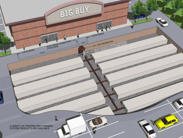
Example of an infiltration chamber system under a parking lot. (Photo Source: CVC, n.d.)
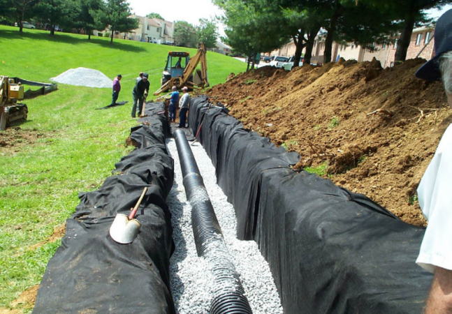
Infiltration trench equipped with a perforated pipe. (Photo Source: Cahill Associates Inc.)[4]
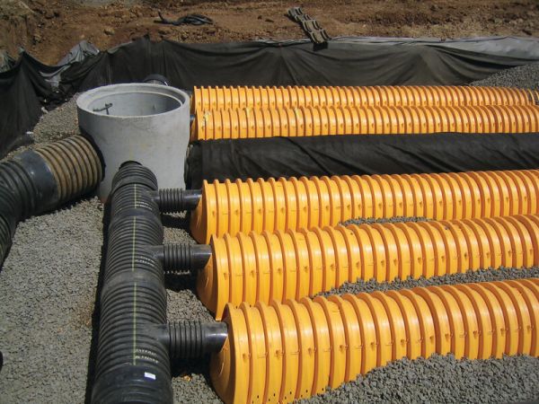
Manifold connecting to infiltration chamber rows. (Photo Source:Advanced Drainage Systems)[5]
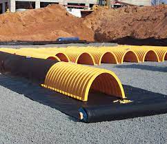
Scour fabric rolled out below an infiltration chamber during assembly. (Photo Source: Advanced Drainage Systems)[6]
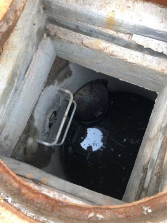
A storm chamber inlet protected from debride by an envirohood. It is essential that the top of the chamber is lower in elevation than any other outlets from the catchbasin. This is because the chamber’s capacity should be fully utilized before runoff is allowed to travel farther downstream. (Photo Source: CVC, 2022)


- ↑ Advanced Drainage Systems. 2022. StormTech® Installation Guide MC-7200 Chamber. https://assets.ads-pipe.com/m/446afe5e1aafda1a/original/MC-7200-StormTech-Chamber-Installation-Guide.pdf
- ↑ Municipal Sewer & Water. 2022. Photo. Accessed in July 8 2022:https://www.mswmag.com/g/product-focus/2015/08/stormwater_management_advanced_drainage_systems_stormtech_mc_4500
- ↑ Makeway Environmental Technologies Inc. 2022. Stormwater Management. Photo. Accessed September 30, 2022: https://www.makeway.ca/products/stormwater-management-systems/
- ↑ Cahill Associates Inc. 2013. Infiltration Trench. Photo. Accessed September 30, 2022: http://www.malvern.org/wp-content/uploads/2013/03/Infiltrench.pdf
- ↑ Advanced Drainage Systems. 2022. StormTech Isolator Row PLUS. Photo. Accessed September 30, 2022: https://www.adspipe.com/water-management-solutions/detention-infiltration/isolator-row
- ↑ Advanced Drainage Systems. 2022. SC-160LP, SC-310, SC-740 & DC-780 Design Manual. Photo. Accessed September 30, 2022: https://assets.ads-pipe.com/m/770e887b972da86f/original/SC-160LP-SC-310-SC-740-DC-780-StormTech-Design-Manual.pdf