Enhanced swales

This article is about installations designed to capture and convey surface runoff along a vegetated channel, whilst also promoting infiltration.
- For underground conveyance which promotes infiltration, see Exfiltration trenches.
- For conveyance along planted channels, on both surface and underground, see Bioswales.
Overview[edit]
Enhanced Grass Swales are vegetated open channels designed to convey, treat and attenuate stormwater runoff. Simple grass channels or ditches have long been used for stormwater conveyance, particularly for road drainage. Enhanced grass swales incorporate design features such as modified geometry and check dams that improve the contaminant removal and runoff reduction functions of simple grass channel and roadside ditch designs. Bioretention swales (i.e.bioswales, dry swales) incorporate filter media and possibly a perforated pipe underdrain to ensure they drain within the required drawdown time. Where development density, topography and depth to water table permit, swales are a preferable alternative to curb and gutter and storm drains as a stormwater conveyance system.
Enhanced swales are an ideal technology for:
- Sloped sites,
- Cheaply retrofitting and improving the performance of existing grass swales.
Take a look at the downloadable Enhanced Grass Swales Factsheet below for a .pdf overview of this LID Best Management Practice:

The fundamental components of an enhanced grassed swale are:
- Graded channel
- Resilient turf grass or other planting
- Check dams, to facilitate short term ponding
Additional components may include:
- Amended soil or filter media to increase infiltration to soils below
- Turf reinforcement, to prevent scour
Planning considerations[edit]
When planning a new site, all swales and overground flow paths should be fitted perpendicular to existing contours. See Natural drainage and Existing hydrology.
Best cross sections[edit]


Enhanced swales aim to both reduce the flow rate and retain a portion of the conveyed water. For these purposes the best x-section is that which maximizes the wetted perimeter for a given area. For a given width and depth, the difference between a triangular and trapzoidal section is small. As shown in the diagrams, under low flow conditions the trapezoidal has greater wetted perimeter, and at higher flows the triangular profile does.
Safety[edit]
As shallow grassed swales are a common roadside construction, the Ministry of Transport has created their own guide to maximum flow depth and freeboard[1][2]. Their advice has been prepared specifically for high risk environments and those stringent constraints should not be applied to all circumstances. In many urban environments the principle of applying check dams to enhance all surface BMPs can be safely used to encourage ponding and subsequent infiltration for a day or two.
Native Soil[edit]
Swales can be located over any soil type, but HSG A and B soils are best for achieving water balance objectives. Facilities should be located in portions of the site with the highest native soil infiltration rates. Where infiltration rates are less than 15 mm/hr (hydraulic conductivity less than 1x10⁻⁶ cm/s) an underdrain is recommended. Native soil infiltration rate at the proposed facility location and depth should be confirmed through in-situ measurements of hydraulic conductivity under field saturated conditions.
Wellhead Protection[edit]
Facilities receiving road or parking lot runoff should not be located within year 2 year time-of-travel wellhead protection areas (see local drinking water source protection plan).
Available Space[edit]
Reserve open space of about 5 to 20% of the size of the contributing drainage area. A width of at least 2 metres is needed
Site Topography[edit]
Contributing slopes should be between 1 to 5%. Swale longitudinal slopes may range from 0.5 to 6% (this prevents ponding while providing residence time and preventing erosion). On slopes steeper than 3%, check dams should be used.
Water Table[edit]
Maintaining a separation of 1 m between the elevations of the base of the practice and the seasonally high water table, or top of bedrock is recommended. Lesser or greater values may be considered based on groundwater mounding analysis. See STEP LID Planning and Design Guide wiki page, Groundwater, for further guidance and spreadsheet tool.
Pollution Hot Spot Runoff[edit]
To protect groundwater from possible contamination, runoff from pollution hot spots (i.e. (e.g., vehicle fueling, servicing and demolition areas, outdoor storage and handling areas for hazardous materials and some heavy industry sites) should not be treated by swales designed for infiltration. Facilities designed with an impermeable liner (filtration only) can be used to treat runoff from hot spots.
Proximity to Underground Utilities[edit]
Designers should consult local utility design guidance for the horizontal and vertical clearance between storm drains, ditches and surface water bodies. Utilities running parallel to the grass swale should be offset from the centerline of the swale. Generally, underground utilities below the bottom of the swale are not a problem.
Karst[edit]
Swales designed for infiltration are not suitable in areas of known or implied karst topography.
Setback from Buildings[edit]
Should be set back a minimum of 4m from building foundations.
Design[edit]
See: Enhanced swales: Specifications for further guidance regarding BMP sizing.
All swales should be designed to meet the following criteria:
- Treat drainage areas of <2 hectares
- Minimum residence time of 5 minutes.
- Maximum flow velocity 0.3 m/s
- Bottom width between 0.75 - 3.0 m
- Minimum length 30 m
- Minimum length between checkdams > 5m
- Maximum depth of flow should be 50% height of grass for regularly mown swales, to a maximum of 100 mm, or 33% height of vegetation for infrequently mown swales
- Cross-section shape may be parabolic or trapezoidal, but parabolic is preferable for aesthetics, maintenance and hydraulics.
Geometry and Site Layout[edit]
Minimum planting soil or filter media bed footprint area is based on the design storm runoff volume and effective surface ponding depth behind check dams. Recommended impervious drainage area to pervious facility footprint area ratios (I:P ratios) range from:
- 5:1 on low permeability soils, such as hydrologic soil group (HSG) C and D,
- 20:1 on high permeability soils hydrologic soil group (HSG) Aand D.
Pre-Treatment[edit]
Pre-treatment captures sediment before it reaches the filter bed. It is typically necessary unless runoff sediment load is very low (e.g. roof drainage). Pre-treatment options include:
- level spreaders
- stone filter inlets with geotextile fabric and,
catch basins with sump.
Planting Soil & Filter Media[edit]
Planting soil or filter media should come pre-mixed from an approved vendor.
Underdrains[edit]
Underdrains are recommended for bioswales where native soil infiltration rate <15 mm/h (hydraulic conductivity < 1x10⁻⁶ cm/s), and needed for non-infiltrating designs. They are comprised of a length of perforated pipe embedded near the top of the storage reservoir, with an overlying choker layer of medium-sized aggregate, and structures to provide inspection and maintenance access. Alternatively, the perforated pipe could be installed on the reservoir bottom and connected to an upturned pipe assembly or riser. Another option is to include a flow restrictor (e.g. orifice cap or valve) on the underdrain outlet pipe, to optimize infiltration while meeting the required drainage time.
Perforated Pipe[edit]
Continuously perforated pipe should be either smooth interior HDPE or PVC pipe with diameter ≥200 mm to reduce freezing risk and facilitate access by camera and cleaning equipment. Perforated pipe extends length of facility and solid pipe is used to connect to storm drain system.
Access Structures[edit]
The use of maintenance holes/vertical standpipes connected to the perforated pipe system are used for inspection and flushing, ensure couplings used for standpipe connections are 45° to facilitate pipe access by camera or cleaning equipment. (See to the right for example of couplings attaching to an underdrain pipe.

Conveyance and Overflow[edit]
Swales can be designed to be inline or offline from the drainage system. Inline swales accepts all flow from the drainage area and conveys large event flows through an overflow outlet. Overflow structures must be sized to safely convey large event flows out of the facility. Options include flat, dome or ditch inlet catch basins connected to a storm sewer.
See: Overflow: Gallery for examples.
Monitoring Wells[edit]
A vertical standpipe consisting of an anchored 100 to 150 mm diameter pipe with perforations along the length within the reservoir, installed to the bottom of the facility, with a lockable cap. The well allows monitoring of inter-event drainage times with the use of a water level data logger sampler.
Planting Considerations[edit]
- Grasses and herbaceous species with dense root structure cover should be favoured along the bottom of the swale for their ability to increase infiltration, stabilize soils, retain pollutants and assist with suspended solids.
- Enhanced grass swales may be planted with sod or seed. Stabilize swale with erosion control blanket if planting with seed. Include a temporary cover crop in native seed mix.
- The plant material on the slopes of grass channels must be capable of withstanding periodic inundation in addition to extended periods of drought. Species include grasses and groundcovers, as well as low shrub species.
- Plants along the exterior of this zone act to slow the flow during stormwater events, reducing sedimentation and increasing infiltration. The root structure of this plant material also acts to reduce erosion.
- Selected grasses or groundcovers for grassed swales should be allowed to grow between 75 to 150 mm to assist in filtering suspended solids from stormwater. Therefore these species are either shorter naturally, or tolerate periodic mowing.
- When grasses grow taller they have a tendency to flatten down from the water flow.
- Fine, close-growing species provide for good soil stabilization.
- Species are salt-tolerant due to the typical location of grass channels along roadways and parking lots.
- Erosion protection such as river stone or riprap will be required to dissipate the energy from incoming concentrated flow.
- The channel must be vegetated immediately after grading. Preferably, the swale should be planted in the spring so that the vegetation can become established with minimal irrigation.
Construction Considerations[edit]
Properly installed enhanced swales should abide by the following recommendations:
- Grass swales should be clearly marked before site work begins to avoid disturbance during construction.
- No vehicular traffic, except that specifically used to construct the facility, should be allowed within the swale site.
- Any accumulation of sediment that does occur within the swale must be removed during the final stages of grading to achieve the design cross section, see above, under the Design section.
- Final grading and planting should not occur until the adjoining areas draining into the swale are stabilized. Flow should also not be diverted into the swale until the banks are stabilized.
- Preferably, the swale should be planted in the spring so that the vegetation can become established with minimal irrigation.
- Installation of erosion control matting or blanketing to stabilize soil during establishment of vegetation is highly recommended.
- If sod is used, it should be placed with staggered ends and secured by rolling the sod. This helps to prevent gullies
Modeling[edit]
![]()


It is recommended that grass and enhanced grass swales be modelled using the 'Swale' element in the TTT. A 'swale' has to connect two existing elements within the TTT Bioswales or dry swales, which have amended filter media, should be modelled as bioretention cells. The alternative is to use the 'enhanced swale' within the LID toolbox, but this incorporates fewer design parameters (and doesn't account for infiltration).
| General Info | |
|---|---|
| Upstream Node | Name of node on the inlet end of the swale (higher elevation) |
| Downstream Node | Name of node on the outlet end of the swale (lower elevation) |
| Manning's Roughness | Lower numbers indicate less surface obstruction and result in faster flow. Suggested range for mown grass (dependent on density) 0.03 – 0.06 [4] |
| Upstream Invert (m) | Depth of swale invert above node invert at inlet end of the swale |
| Downstream Invert (m) | Depth or elevation of the swale invert above the node invert at the outlet end of the swale |
| Cross section | |
| Maximum Depth (m) | Depth of the swale |
| Bottom Width (m) | Bottom width of the trapezoidal swale For a triangular channel, enter 0 |
| Left Side Slope (m/m) | Left side slope (run/rise). Suggested value of 3 or 4 if design permits. |
| Right Side Slope (m/m) | Right side slope (run/rise). Suggested value of 3 or 4 if design permits. |
| Seepage (mm/hour) | Infiltration rate of native (or amended) soil |
| Surface | |
|---|---|
| Berm height (mm) | This is the height of the curb which constrains the overland sheet flow of water. Where the bottom of the slope discharges directly into another LID facility without impedance, the value is 0. |
| Surface roughness (Manning’s n) | Lower numbers indicate less surface obstruction and result in faster flow. Suggested range for mown grass (dependent on density) 0.03 – 0.06 [4] |
| Surface slope (%) | If the slope > 3%, use Check dams to create temporary ponding, increase infiltration, and slow flow to reduce erosion. |
| Swale side slopes (run/rise) | Suggested value of 3 or 4 if design permits. |
Materials[edit]
Resilient turf grasses are particularly useful in the design of vegetated filter strips, dry ponds and enhanced grass swales. The Ministry of Transportation have standardized a number of grass mixes[5]. The 'Salt Tolerant Mix' is of particular value for low impact development applications alongside asphalt roadways and paved walkways.
| Common name | Scientific name | Proportion |
|---|---|---|
| Tall Fescue | Festuca arundinacea | 25 % |
| Fults Alkali Grass | Puccinellia distans | 20 % |
| Creeping Red Fescue | Festuca rubra | 25 % |
| Perennial ryegrass | Lolium perrenne | 20 % |
| Hard Fescue | Festuca trachyphylla | 10 % |


For advice on aggregates used in underdrains, see Reservoir aggregate.
Stone or gravel can serve as a low maintenance decorative feature, but it may also serve many practical functions on the surface of an LID practice.
Stone for erosion control[edit]
Aggregates used to line swales or otherwise dissipate energy (e.g. in forebays) should have high angularity to increase the permissible shear stress applied by the flow of water. [6] However, in some surface landscaped applications there may be a desire to use a rounded aggregate such as 'river rock' for aesthetic reasons. Rounded stones should be of sufficient size to resist being moved by the flow of water. Typical stone for this purpose ranges between 50 mm and 250 mm in diameter. The larger the stone, the more energy dissipation.
- Stone beds should be twice as thick as the largest stone's diameter.
- If the stone bed is underlain by a drainage geotextile, annual inspection and possible replacement should be performed as there is a potential for clogging of this layer to occur.
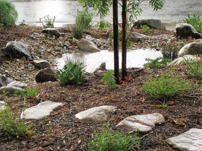
Stone lining the ponding zone of this rain garden. Image credit California Native Plant Society

Coarse angular stone laid onto a geogrid and geotextile. Image from wikimedia commons


Stone mulch[edit]
Finer inorganic mulch materials can be of value applied in areas with extended ponding times i.e. in the the centre of recessed, bowl shaped bioretention, stormwater planters, trenches or swale practices. Inorganic mulches resist movement from flowing water and do not float. Applying a thin layer of inorganic mulch over the top of wood based mulch has been shown to reduce migration of the underlying layer by around 25% [7]. Inorganic mulches which may be available locally, include:
- Pea gravel
- River rock/beach stone
- Recycled glass
- Crushed mussel shells
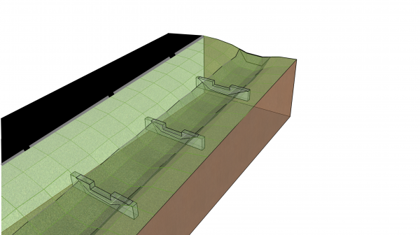
Check dams[edit]
Check dams are small dams or weirs constructed across a drainage ditch, swale, or channel to lower the speed of concentrated flows for a certain design range of storm events and to promote infiltration.
Check dams:
- may be constructed of any resilient and waterproof material, including: rock gabions, earth berms, coarse aggregate or rip-rap, concrete or metal. Stone used in check dams should have minimum median diameter 25 - 75 mm.
- for enhanced swales may be up to 0.6 m in height; the maximum design depth of ponded water should be ≤ 0.6 m.
- designed for higher flow velocities should have spillways incorporated into their profile, to direct water to the centre of the swale.
- are usually installed between 10 - 20 m along the swale. The spacing of dams should not exceed the horizontal distance from the toe of the upstream dam to the same elevation on the downstream dam.
- should have energy dissipation and erosion control measures installed in the 1 - 2 m downstream. Examples include large aggregate or turf reinforcement
Sizing and spacing of check dams[edit]

Check dams are a feature of enhanced grass swales. They promote infiltration and evaporation by promoting limited ponding. To design check dams into a swale:
- The height of each dam is determined by the depth of ponded water that will infiltrate in a specified period (often 48 - 72 hours). The infiltration may be through the turf grass or other plants directly into the native soil or some soil amendments may be proposed in the design.
- The gradient between the top of the lower check dam and the bottom of the upper one is called "compensation gradient" which is the future or final effective gradient of the swale. It is formed when material carried by flowing water fills the check dams to spillway level.
- Dams are usually installed between 10-20 m along the swale. The spaces between check dams can be determined according to the compensation gradient and the effective height of the dams. They are distributed such that the crest of each dam is at approximately the same elevation as the toe of the upstream dam. If the slope along the swale varies, so should the distance between the dams.
- The compensation gradient of enhanced swales must be < 1 % (0.5 % preferred).
The objective of these design recommendations are to maximize the distribution of ponded water along the whole BMP. Detailed design may require iteration of the dam heights and distances along each section of a long swale.
To estimate the depth of water that can be infiltrated into a surface within a given time:

Where:
- y = the depth of ponded water in mm,
- f' = the design infiltration rate in mm/hr (after correction, where required).
- t = time in hrs
After surveying the longitudinal profile of the swale, the number of check dams for the swale can be calculated by using the following equation:

Where:
- L: Length of swale (m)
- Si: Initial existing slope ratio of the swale (rise/run)
- Se: Desired effective slope of the enhanced swale (between 0.005 - 0.01, rise/run)
- h: The average effective height of the check dams in m (excluding foundations)(suggest you use y, calculated above)
- The first check dam should be constructed on a stable point in the gully such as a rock outcrop, the junction point of the gully to a road, the main stream or river, lake or reservoir.
- If there is no such stable point, a counter-dam must be constructed. The distance between the first dam and the counter-dam must be at least two times the effective height of the first check dam.
- The points where the ensuing check dams are to be built are determined according to the compensation gradient and the effective height of the check dams.
- The effective height of the second check dam is determined by taking into account the depth of the swale, the depth of the spillway and the maximum height of the check dam.
- In this way, all the other proposed check dam points can be calculated.
When spacing check dams, give preference to the narrowest parts of the swale in order to reduce construction costs. In this case, to establish the compensation gradient between the proposed check dams, proportionately increase the foundation depth of the upper check dam when the space between the lower and upper check dam is extended. When the space is shortened, decrease the foundation depth. As the foundation depth is increased, the total height of the check dam (effective height plus foundation depth) should not exceed the permissible, maximum total height.
Example Calculation[edit]
An enhanced swale of 42 m has an existing longitudinal slope of 6 %. The underlying soil has been amended to infiltrate at 16 mm/hr (after safety correction applied); the regulatory authority requires that ponded water must not remain for over 48 hours. The maximum height of the check dams (h) to prevent extended ponding is::

But the maximum recommended depth of check dams is 0.6 m (600 mm).
(As an aside, these will drain in )

The current vertical distance along the swale is::

The desired effective slope to slow flow is 0.5%. The vertical distance along the swale with compensation gradient is::

The number of check dams required is::

This is rounded up to 4 dams, creating 5 ponding zones::

So the four check dams will be 0.6 m high and spaced every 8.4 m along the swale. These are fairly close together, but this construction is achievable and the dimensions are not remarkable, given the change in gradient is an order of magnitude.
Gallery[edit]
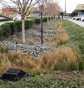
Enhanced swale with rocky check dams and a metal overflow grate in Northgate Mall parking lot, Seattle. Photo credit: MLSmith
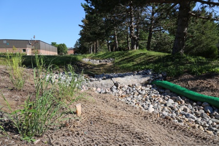
Bioswale with rock check dams to slow down the water, encouraging infiltration. Note the biodegradable erosion control blanket still in place. LSRCA headquarters, 2017
A check dam in action, effectively pooling water.
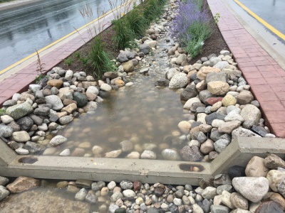
A swale during a rain event, with concrete check dams, armourstone, mulch and Tall grasses to slow down moving water (as shown in the .gif file) to promote infiltration in the feature.


Also see Jen's Pinterest board of check dams
External references[edit]
Performance[edit]
| BMP | Water Balance | Water Quality | Erosion Control |
|---|---|---|---|
| Swale with no underdrain | Partial-based on available storage volume and native soil infiltration rate | Yes-size for water quality storage requirement and maximum flow rate 0.5 m/s | Partial-based on available storage volume and native soil infiltration rate |
| Swale with underdrain or partial infiltration | Partial-based on available storage volume beneath the underdrain and soil infiltration rate | Yes-size for water quality storage requirement | Partial-based on available storage, native soil infiltration rate and if a flow restrictor is used |
| Swale with underdrain and impermeable liner or no infiltration | Partial-some volume reduction through evapo-transpiration | Yes-size for water quality storage requirement | Partial-based on available storage volume and if a flow restrictor is used |
Water Balance[edit]
Recent research indicates that a conservative runoff reduction rate of 10 to 20% can be used depending on whether soils fall in hydrologic soil groups A/B or C/D, respectively. The runoff reduction rates can be doubled if the native soils on which the swale is located have been tilled to a depth of 300 mm and amended with compost to achieve an organic content of between 8 and 15% by weight or 30 to 40% by volume. The main contributing factors that influence runoff reduction rates for swales are:
- Native soil types
- Slope
- Vegetative cover and,
- Length of the swale.
| LID Practice | Location | Runoff Reduction* | Reference |
|---|---|---|---|
| Grass Swale | Brampton | 15 to 35%, | STEP (2018)[8] |
| Sweden | 40 to 55%, | Rujner et al. (2016)[9] | |
| Seoul, Korea | 40 to 75%, | Rujner et al. (2016)[10] | |
| Maryland | 59% | Davis et al. (2012)[11] | |
| Los Angeles | 52.5%, | Ackerman and Stein (2008)[12] | |
| Various Locations | 40% | Strecker et al.(2004)[13] | |
| France | 27 to 41% | Barrett et al. (2004)[14] | |
| Virginia | 0% | Schueler (1983)[15] | |
| Runoff Reduction Estimate* | 45% on HSG A or B soils;
10% on HSG C or D soils | ||
Water Quality[edit]
Research has shown the pollutant mass removal rates of grass swales are variable, depending on influent pollutant concentrations (Bäckström et al., 2006)[16], but generally moderate for most pollutants (Barrett et al., 1998[17]; Deletic and Fletcher, 2006[18]). Median pollutant mass removal rates of swales from available performance studies are 76% for total suspended solids, 55% for total phosphorus, and 50% for total nitrogen (Deletic and Fletcher, 2006[19]). Significant reductions in total zinc and copper event mean concentrations have been observed in performance studies with a median value of 60%, but results have varied widely (Barrett, 2008[20]). Site specific factors such as slope, soil type, infiltration rate, swale length and vegetative cover also affect pollutant mass removal rates. In general, the dominant pollutant removal mechanism operating in grass swales is infiltration, rather than filtration, because pollutants trapped on the surface of the swale by vegetation or check dams are not permanently bound (Bäckström et al., 2006[21]). In a recent international research review on processes for improving stormwwater quality treatment of grass swales and vegetated filter strips, Gavric et al. note that while understanding of hydrology and hydraulics of these stormwater control measures is adequate, there are knowledge gaps in understanding water quality treatment processes, particularly for nutrients, traffic associated organic contaminants, and bacteria (Gavric et al., 2019 [22]). Designers should maximize the degree of infiltration achieved within a grass swale by incorporating check dams and ensuring the native soils have infiltration rates of 15 mm/hr or greater or specifying that the soils be tilled and amended with compost prior to planting. Several of the factors that can significantly increase or decrease the pollutant removal capacity of swales are provided in the table below:
| Factors that Reduce Removal Rates | Factors that Enhance Removal Rates |
|---|---|
| Longitudinal slope > 1% | Longitudinal slope < 1% |
| Measured soil infiltration rate < 15 mm/hr | Measured soil infiltration rate is 15 mm/hr or greater |
| Flow velocity within channel > 0.5 m/s during a 4 hour, 25 mm Chicago storm event | Flow velocity within channel is 0.5 m/s or less during a 4 hour, 25 mm Chicago storm event |
| No pretreatment | Pretreatment with vegetated filter strips, gravel diaphragms and/or sedimentation forebays |
| Side slopes steeper than 3:1 (H:V) | Side slopes 3:1 (H:V) or less |
- ↑ Ontario Ministry of Transportation, & Ontario Ministry for Transportation. (2016). Stormwater Management Requirements for Land Development Proposals. Retrieved February 26, 2018, from http://www.mto.gov.on.ca/english/publications/drainage/stormwater/section8.shtml#controls
- ↑ Drainage and Hydrology Section Transportation Engienering Branch Quality and Standards Division. (1997). MTO Drainage Management Manual. Retrieved from http://www.ontla.on.ca/library/repository/mon/12000/198363.pdf
- ↑ Horry County Government. 2022. Stormwater Engineers - Plans and the Construction Process. https://www.horrycounty.org/Departments/Stormwater/engineers
- ↑ Jump up to: 4.0 4.1 Oregon State Univ., Corvallis. Dept. of Civil, Construction and Environmental Engineering.; Environmental Protection Agency, Cincinnati ONRMRL. Storm Water Management Model Reference Manual Volume I Hydrology (Revised). 2016:233.https://nepis.epa.gov/Exe/ZyPURL.cgi?Dockey=P100NYRA.txt Accessed August 23, 2017.
- ↑ Ontario Provincial Standard Specification. (2014). Construction Specification and for Seed and Cover OPSS.PROV 804. Retrieved from http://www.raqsb.mto.gov.on.ca/techpubs/ops.nsf/0/3a785d2f480f9349852580820062910a/$FILE/OPSS.PROV 804 Nov2014.pdf
- ↑ Roger T. Kilgore and George K. Cotton, (2005) Design of Roadside Channels with Flexible Linings Hydraulic Engineering Circular Number 15, Third Edition https://www.fhwa.dot.gov/engineering/hydraulics/pubs/05114/05114.pdf
- ↑ Simcock, R and Dando, J. 2013. Mulch specification for stormwater bioretention devices. Prepared by Landcare Research New Zealand Ltd for Auckland Council. Auckland Council technical report, TR2013/056
- ↑ Sustainable Technologies Evaluation Program. Effectiveness of Retrofitted Roadside Biofilter Swales - County Court Boulevard, Brampton. Technical Brief. https://sustainabletechnologies.ca/app/uploads/2020/11/CC-Bioswale-Tech-brief-2018-FINAL.pdf. https://sustainabletechnologies.ca/app/uploads/2020/11/CC-Bioswale-Tech-brief-2018-FINAL.pdf
- ↑ Rujner, H., Leonhardt, G., Perttu, A.M., Marsalek, J. and Viklander, M. 2016. Advancing green infrastructure design: Field evaluation of grassed urban drainage swales. Modélisation/Models-Contrôle à la source/Source control. http://documents.irevues.inist.fr/bitstream/handle/2042/60477/3B7P03-124RUJ.pdf
- ↑ Rujner, H., Leonhardt, G., Perttu, A.M., Marsalek, J. and Viklander, M. 2016. Advancing green infrastructure design: Field evaluation of grassed urban drainage swales. Modélisation/Models-Contrôle à la source/Source control. http://documents.irevues.inist.fr/bitstream/handle/2042/60477/3B7P03-124RUJ.pdf
- ↑ Davis, A.P., Stagge, J.H., Jamil, E. and Kim, H. 2012. Hydraulic performance of grass swales for managing highway runoff. Water research, 46(20), pp.6775-6786. http://www.jstagge.com/assets/papers/Hydraulic%20performance%20of%20grass%20swales%20for%20managing.pdf
- ↑ Ackerman, D. and Stein, E.D. 2008. Evaluating the effectiveness of best management practices using dynamic modeling. Journal of Environmental Engineering, 134(8), pp.628-639. https://www.researchgate.net/profile/Eric-Stein-2/publication/228910558_Evaluating_the_Effectiveness_of_Best_Management_Practices_Using_Dynamic_Modeling/links/0912f509278915fc77000000/Evaluating-the-Effectiveness-of-Best-Management-Practices-Using-Dynamic-Modeling.pdf
- ↑ Strecker, E., Quigley, M., Urbonas, B., Jones, J. 2004. State-of-the-art in comprehensive approaches to stormwater. The Water Report. Issue 6. August 15,2004.
- ↑ Barrett, M.E. 2008. Comparison of BMP Performance Using the International BMP Database. Journal of Irrigation and Drainage Engineering. September/October. pp. 556-561
- ↑ Schueler, T. 1983. Washington Area Nationwide Urban Runoff Project. Final Report. Metropolitan Washington Council of Governments. Washington, DC.
- ↑ Bäckström, M., Viklander, M. and Malmqvist, P.A. 2006. Transport of stormwater pollutants through a roadside grassed swale. Urban Water Journal, 3(2), pp.55-67. https://www.mdpi.com/2073-4441/6/7/1887/htm
- ↑ Barrett, M.E., Walsh, P.M. Malina Jr., J.F. and Charbeneau, R.J. 1998. Performance of Vegetative Controls for Treating Highway Runoff. Journal of Environmental Engineering. November 1998. pp. 1121-1128.
- ↑ Deletic, A., and Fletcher, T.D. 2006. Performance of grass filters used for stormwater treatment – a field and modelling study. Journal of Hydrology. Vol. 317. pp. 261-275.
- ↑ Deletic, A., and Fletcher, T.D. 2006. Performance of grass filters used for stormwater treatment – a field and modelling study. Journal of Hydrology. Vol. 317. pp. 261-275.
- ↑ Barrett, M.E. 2008. Comparison of BMP performance using the international BMP database. Journal of Irrigation and Drainage Engineering, 134(5), pp.556-561.
- ↑ Bäckström, M., Viklander, M. and Malmqvist, P.A. 2006. Transport of stormwater pollutants through a roadside grassed swale. Urban Water Journal, 3(2), pp.55-67. https://www.mdpi.com/2073-4441/6/7/1887/htm
- ↑ Gavric.S, Leonhardt, G., Marsalek, J., Viklander, M. 2019. Processes improving urban stormwater quality in grass swales and filter strips: A review of research findings. Science of the Total Environment. v 669. pp. 431-447. https://www.sciencedirect.com/science/article/pii/S0048969719310502?via%3Dihub