Infiltration Chamber: Life Cycle Costs
Overview[edit]
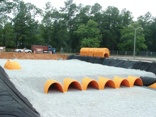
Infiltration chambers include a range of proprietary manufactured, modular structures installed underground (embedded in clean, crushed angular stone) to create large void spaces that temporarily store and infiltrate runoff into the underlying native soil. Typically installed under parking or landscaped areas, they can be used in various configurations. They are well suited to sites where available land area is limited, or where it is desirable for the facility to have a minimal surface footprint. They can be designed with enough load bearing capacity to support the weight of structures above them, meaning that they can be installed below parking lots, sports fields, etc. STEP has prepared life cycle costs estimates for each design configuration, based on a 2,000 m2 road drainage area, runoff control target of 25 mm depth and 72 hour drainage period, for comparison which can be viewed below. To generate your own life cycle cost estimates customized to the development context, design criteria, and constraints applicable to your site, access the updated LID Life Cycle Costing Tool (LCCT) here.
Design Assumptions[edit]
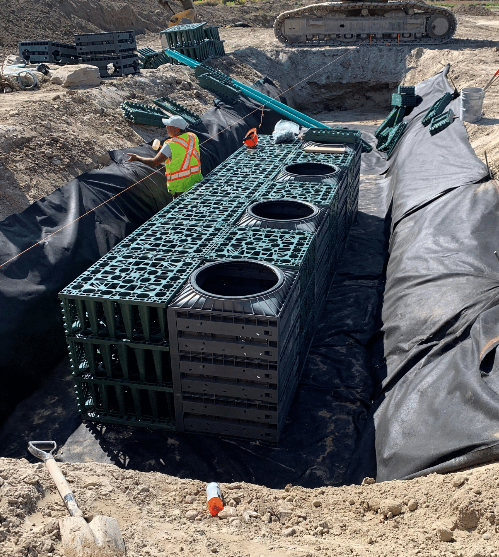
Infiltration chambers are an ideal technology for installing below any type of surface or landscape and for receiving and infiltrating large volumes of water. Components include: washed 25 or 50 mm diameter crushed angular stone to create a suitable storage reservoir, proprietary chambers, vaults, crates or perforated pipes that provide large water storage volume per unit area, geotextile, perforated pipe or underdrains and access structures.
Design and operation and maintenance program assumptions used to generate cost estimates are based on tool default values and the following STEP recommendations:
- Native soil infiltration rates for Full, Partial and No Infiltration Design scenarios were assumed to be 20 mm/h, 10 mm/h and 2 mm/h, respectively, and a safety factor of 2.5 was applied to calculate the design infiltration rate.
- Operation and maintenance (O&M) cost estimates assume annual inspections, removal of trash and debris twice a year, removal of sediment from pretreatment structures annually, and removal of weeds twice a year (where applicable). Verification inspections are included every 5 years to confirm adequate maintenance, and every 15 years to confirm adequate drainage performance through in-situ surface infiltration rate testing (where applicable)
- Designed with an impervious drainage area to treatment facility area ratio of between 5:1 and 20:1.
- A maximum ratio of 10:1 is recommended from facilities receiving road or parking lot runoff.
- Facilities receiving road or parking lot runoff should not be located within the two year time-of-travel of wellhead protection areas.
- Facilities cannot be located on natural slopes greater than 15%.
- The bottom of the facility should be vertically separated by one metre from the seasonally high water table or top of bedrock elevation.
- Facilities should be setback a minimum of four metres from building foundations.
- Pretreatment device options include leaf screens for roof runoff, and vegetated filter strips, grass swales or oil and grit separators for road runoff.
- The tool automatically includes an OGS for facilities receiving road runoff.
- The inlet and overflow outlet to the facility should be installed below the maximum frost penetration depth to prevent freezing.
- The overflow outlet can be the pipe inlet that backs up when capacity's reached (discharging to pervious area), or it can be a pipe connected to a storm sewer.
- Outlet pipes must have capacity equal to or greater than the inlet.
- Capped and vertical non-perforated pipes connected to the inlet and outlet pipes are recommended for inspecting and flushing as part of routine maintenance.
- Manholes and inspection ports should be installed in infiltration chambers to provide access for monitoring and maintenance activities (Tool defaults).
- Compaction, erosion and sediment control are main concerns during construction. Facilities are vulnerable to failure during the construction phase. Construction sediment can clog the excavation if construction instructions incorrectly followed.
Notes[edit]
- Designs include pretreatment through hydrodynamic separator (Oil and Grit Separator and A "Sediment Trap" or Isolated chamber row).
- The tool calculates costs for new (greenfield) development contexts and includes costs for contractor overhead and profit, material, delivery, labour, equipment (rental, operating and operator costs), hauling and disposal.
- Land value and equipment mobilization and demobilization costs are not included, assuming BMP construction is part of overall development site construction.
- Design and Engineering cost estimates are not calculated by the tool and must be supplied by the user.
- The tool adds 10% contingency and additional overhead as default.
- All cost estimates are in Canadian dollars and represent the net present value (NPV) as the tool takes into account average annual interest and discount rates over the 25 and 50 year operating life cycle periods.
- Unit costs are based on 2018 RSMeans standard union pricing.
- Cost for piping from roof to system, parking lot to system and overflow from system are not included in this costing.
- Costs of the control manhole and overflow, and pre-treatment via an OGS (when the facility takes road runoff) are included.
- Additional costs associated with retrofit or redevelopment contexts is assumed to be 16% of the cost estimate for new (greenfield) construction contexts.
- Retrofit construction cost estimates are included in the 'Costs Summary' section for comparison.
- Retrofit construction cost estimates are included in the 'Costs Summary' section for comparison.
Construction Costs[edit]
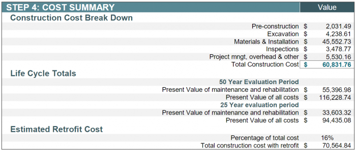
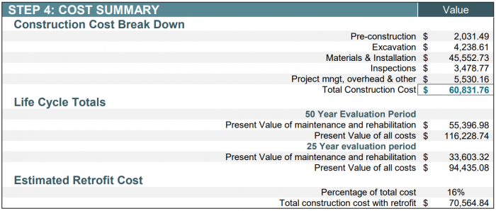
Note: Please click on each image to enlarge to view associated construction cost estimates.
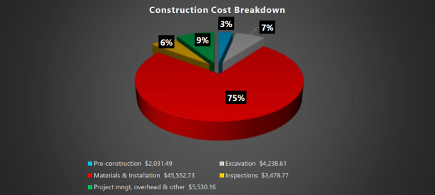
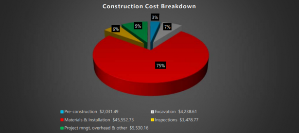
Above you can find a cost breakdown of a 1000m2 in two different configurations:
As can be seen, regardless of design configuration, Material & Installation expenses represent the largest portion of total construction costs (75%).
Life Cycle Costs[edit]
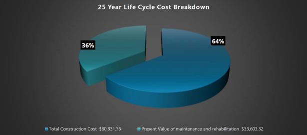
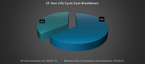
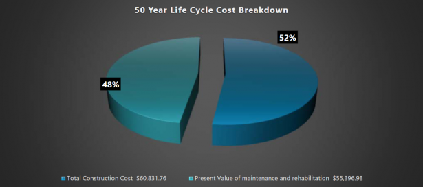
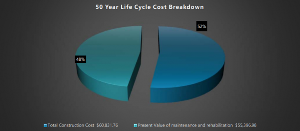
Below are capital and life cycle cost estimates for the two infiltration chamber configurations over 25- and 50-year time periods. The estimates of maintenance and rehabilitation (life cycle) costs represent net present values. Operation and maintenance costs are predicted to represent 36% of total life cycle costs over the 25-year evaluation period, and increase to 48% of total life cycle costs over the 50-year period, due to increased levels of litter removal, clean out and disposal of collected sediment from the Isolated chamber row (every 4 - 8 years), cleaning out the catchbasin and the Oil and Grit Separator/Hydrodynamic Separator annually.
25-Year life cycle cost break down[edit]
Note: Click on each image to enlarge to view associated life cycle cost estimate.
50-Year life cycle cost break down[edit]
Note: Click on each image to enlarge to view associated life cycle cost estimate.
Cost Summary Tables[edit]
Total life cycle cost estimates for the two infiltration chamber configurations are the exact same with the total being ($60,831.76).
It is notable that a sensitivity analysis was conducted in 2019 to compare construction cost estimates generated by the tool to actual costs of implemented projects. The analysis found that tool estimates were typically within ±14% of actual construction costs[2]
Full Infiltration[edit]
Partial Infiltration[edit]
References[edit]
- ↑ Young, D. Van Seters, T., Graham, C. 2013. Evaluation of Underground Stormwater Infiltration Systems. Toronto and Region Conservation Authority. Toronto, Ontario. https://sustainabletechnologies.ca/app/uploads/2013/03/Infiltration-Chambers-and-Trenches_2013-Final.pdf
- ↑ Credit Vally Conservation (CVC). 2019. Life-cycle costing tool 2019 update: sensitivity analysis. Credit Valley Conservation, Mississauga, Ontario. https://sustainabletechnologies.ca/app/uploads/2020/04/LCCT-Sensitivity-Analysis_March2020.pdf
