Treatment trains

Overview[edit]
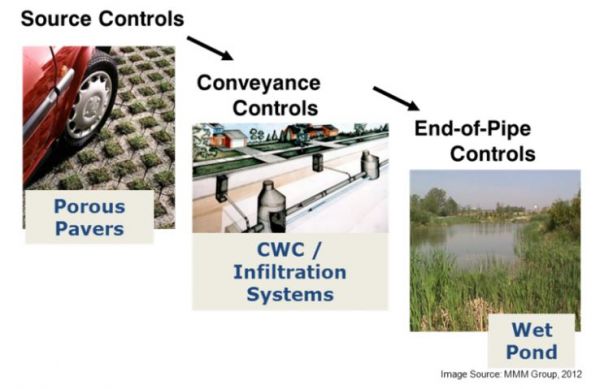
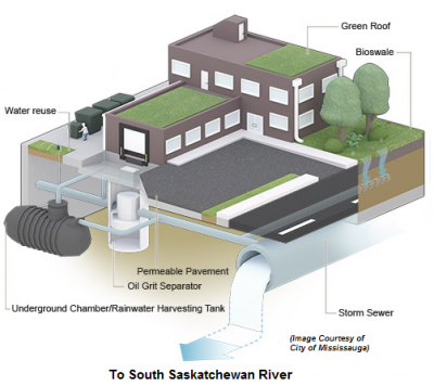
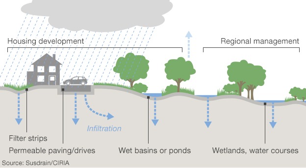
A treatment train uses a combination of lot-level or source (LID), conveyance and/or end-of-pipe practices to meet water quality, water quantity, water balance, and erosion design criteria for the site. These may be implemented to reduce the burden of facility maintenance, address a broader range of design criteria, increase overall treatment system performance, and/or control the rate of flow through downstream facilities.
| Type of Control/Practice | Lot-Level Source Controls & Conveyance Practices | End-Of Pipe Facilities |
|---|---|---|
| Storage |
|
|
| Infiltration |
|
|
| Pretreatment | ||
| End-of-Pipe / Flood & Erosion Control |
Types of Treatment Train Designs[edit]
Examples of applications designed to address specific objectives include the following listed in the corresponding sections below:
1. Treatment trains designed to reduce maintenance burdens[edit]
These are the most common types of treatment trains. They typically involve installation of one or more pretreatment devices upstream or at the inlet of the primary stormwater treatment facility.

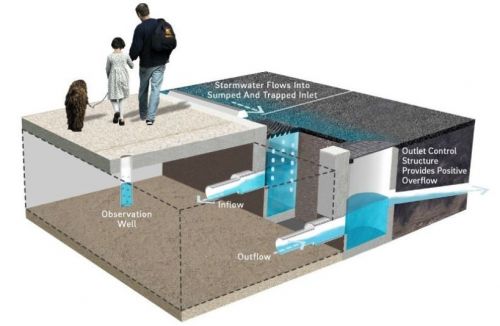
Example: Runoff into larger treatment practices such as bioretention or stormwater tree trenches may be pretreated by concrete sumps at curb cut inlets, forebays or catch basin inserts, which are designed to capture coarse sediment, debris and trash. Centralizing sediment and trash captured at the inlet or entrance to the facility reduces maintenance by preventing filter media clogging and limiting the area over which sediment and trash needs to be removed. In some cases, pre-treatment device clean-outs may be incorporated into existing municipal catch basin cleaning programs.
Performance calculation: If the downstream facility provides filtration, such as bioretention or stone filled trenches, the overall water quality performance of this facility would not increase with pretreatment because the coarse sediment and debris captured by the pretreatment device would be removed by the downstream facility even in the absence of pretreatment. The purpose of adding pre-treatment is to prevent clogging or filling and thereby reduce the cost and effort of long term maintenance and delay requirements for major facility rehabilitation or replacement.

2. Treatment trains designed to address one or more design criteria[edit]
These types of treatment trains combine practices that address different design criteria, in recognition that most individual stormwater facility types do not meet all design criteria as stand-alone facilities. For instance, stormwater wet ponds may provide water quality, erosion and flood control but not water balance control (i.e. runoff volume control). Bioretention provides good water quality and water balance control but are rarely designed for flood control.
Example: Proprietary filtration treatment device (providing water quality) draining to an underground infiltration trench or chamber system (providing water balance control). Overflows from the trench or chamber system could drain to a dry pond or other flood control facility to provide water quantity and erosion control). Another example may be to direct low flows from a stormwater management pond outlet to an infiltration practice.
Performance calculation: Treatment trains designed to address multiple design criteria may improve overall water quality performance by, for example, reducing water quality concentrations in the first facility and reducing water quality loads (through infiltration/evapotranspiration) in a second facility. Even if the effluent concentration from facility one and facility two are the same, the overall load reduction of the treatment train may be greater than provided by any one of the facilities alone.
3. Treatment trains designed to enhance overall treatment system performance[edit]

The design intent of these treatment trains is to enhance overall system performance. The previous category of treatment train may enhance performance, but the objective may not always be to address a broader range of stormwater criteria.
Example: A bioretention and infiltration chamber in series. Adding the second facility increases the overall area available for infiltration, which in turn reduces the overall load of pollutants to the receiver. This type of treatment may be advantageous where surface space is limited, but water balance requirements can not be met with available space allocated to the surface bioretention cell alone.
Performance calculation: In the example above, the bioretention facility would provide water quality load reductions through filtration (water quality concentration reductions) and infiltration (volume reductions). Since the second facility would receive effluent from the underdrain of the bioretention, no further reduction in TSS concentrations would be expected (ie. the TSS concentration would already be at the ‘irreducible’ level) (Schueler, 2000)[5]. The TSS water quality load would be reduced in the second facility only by further reductions in volumes through infiltration. If the parameter of interest was total phosphorus (TP) rather than TSS, there is the potential that the second facility may further reduce TP through filtration/adsorption, especially if the second facility contained reactive media designed to remove phosphorus.
4. Treatment trains designed to optimize treatment facility sizing through flow control[edit]
Upstream controls in this type of treatment train are intended to control flow rates to one or more downstream facilities rather than provide treatment. Controlling the rate of flow to the downstream facility allows it to either be sized for a lower treatment flow rate than would otherwise be the case (which reduces costs) or enhance the performance of the downstream facility by slowing the rate of inflows (treatment practices often perform better at lower inflow rates) and reducing the frequency of bypass flows.
Example: A filtration facility drained by a catchment with temporary upstream water storage through oversized storm sewer pipes, parking lot storage and/or orifice controlled roof drains. In the case of oversized storm sewers or parking lot storage, the pipe feeding the filtration facility would normally have an orifice to control flow rates draining into the facility.
Performance calculation: The capacity of this type of treatment train to improve performance depends on sizing of the downstream practice. If this practice (e.g. proprietary filtration MTD) is sized to the new controlled flow rate (and the design storm remains the same), then the performance of the facility may be the same or similar to what would have been achieved without upstream controls because there would be a similar number of overflows (i.e flows that bypass the treatment chamber). If the downstream practice is a settling device, such as an OGS, then the performance of the downsized facility may be slightly lower than without flow controls because performance of these devices are more sensitive than filters to the rate of flow through the treatment chamber (see performance curves and sizing tool for calculations below).
Of course, the real world is not black and white, and it is possible to blend these categories to meet a variety of different site stormwater management objectives. The purpose of categorizing the treatment train types into design priorities is to highlight the need to consider different objectives, while recognizing that if the design priority of the treatment train is narrowly focused, objectives other than those targeted may not be met.
Calculating Performance of Treatment Trains[edit]
The performance of a treatment train will vary based on the type of stormwater treatment practices implemented and their arrangement within the treatment train. Various changes occur as runoff moves through the treatment train. Key changes that need to be considered when calculating treatment train performance including:
1. Changes in the composition of runoff, especially the size distribution of sediment particles[edit]
Stormwater facilities are often designated as providing enhanced (80% TSS removal) or basic treatment (50 to 60% TSS removal) based on their capacity to remove fine particles (MOE, 2003)[6]. These facilities change not only sediment loads of sediment but also the composition of sediment loads, which has important implications for calculating performance.
2. Changes in influent concentration[edit]
Removal efficiency calculations are sensitive to influent concentration because facility effluent concentrations cannot be reliably reduced beyond a certain level, which varies by facility type. For example, a pond may have an ‘irreducible’ effluent concentration of 30 mg/L for an average rainfall year. If the TSS influent concentration to the pond is 200 mg/L, the pond removal efficiency would be 85%. If the treatment practice(s) upstream of the pond reduce the pond influent concentration to only 100 mg/L, the TSS removal efficiency of pond would only be 70%. This value may be even lower if the 100 mg/L contains a higher percentage of fine particles than untreated runoff (which is often the case).
3. Changes in runoff volume[edit]
Where runoff is being reduced along the treatment train through infiltration and evapotranspiration, there will be a change in water quality loading that needs to be considered.
The water quality load is the product of runoff concentrations and runoff volumes. Hence, a change in either of these variables will result in a change in load. As concentrations and volumes are affected by different variables it is best to consider the components separately, and then combine them to calculate overall load based performance for the treatment train under consideration.
Calculations for Load Based Performance[edit]
Treatment performance of facilities designed to reduce runoff volumes would be calculated based on their capacity to reduce water quality loads, as seen below:
Equation 1:[edit]
Where:
- RL = Removal Efficiency (%)
- AL = storm influent concentration x storm influent volume (mg/L x L)
- BL = storm effluent concentration x storm effluent volume (mg/L x L)
Equation 2:[edit]
Where:
- R = Removal Efficiency (%)
- A = Flow proportioned influent concentration (mg/L)
- B = Flow proportioned effluent concentration (mg/L)
Simple treatment train equations that apply the pollutant removal efficiency of the downstream treatment practice to the fraction of load remaining after passing through the upstream treatment practice, or those that assign downstream practices half the removal efficiency of the upstream practice are not recommended. Instead, the configuration and type of treatment train should be considered on a case by case basis, with consideration for changes in influent runoff concentration/composition and runoff volume as water drains through the different practices. Some examples are provided in the sections below.
Treatment trains without runoff volume reduction[edit]
As noted above, non-infiltrating stormwater facilities are often designated as enhanced or basic treatment based on their capacity to remove total suspended solids (TSS). Enhanced level facilities are credited with 80% TSS removal while basic level facilities are credited with 60% TSS removal or less.
Basic level facilities are typically placed upstream of enhanced level facilities in treatment trains because enhanced level facilities remove the coarse sediment particles that would otherwise be removed by the basic level facility, as well as finer sediment particles. Placing the level two facility downstream of the level one facility would, therefore, not enhance TSS removal, although it may enhance removal of other pollutants depending on the design components.
Since basic level facilities remove TSS particles that are effectively removed by enhanced level facilities, the removal efficiency of a treatment train consisting of two non-infiltrating facilities would be equal to the removal efficiency of the highest performing facility (i.e. 80% TSS removal), assuming that the facilities are sized appropriately.
Examples of this type of treatment train would include: (i) catch basin inserts (aka water quality inlets) upstream of a filtration facility (e.g. lined bioretention, proprietary filtration system, sand filter); (ii) OGS upstream of a wet pond; (iii) temporary parking lot or pipe storage upstream of a filtration facility. If an OGS is placed upstream of a dry pond, the overall treatment performance would be equal to that of the dry pond since the finer particle size fraction of TSS is not captured. As mentioned above, the major benefit of these types of treatment trains is to reduce long term maintenance cost and effort by centralizing sediment in the upstream practice where it is easier to clean out.
In some cases, it may be advantageous to include two level one facilities in a treatment train. An example may be a lined bioretention with pre-treatment upstream of a filter with media designed to enhance phosphorous uptake. The overall phosphorus removal rate for the treatment train would be equivalent to that of the downstream filter, assuming that it is sized appropriately for the site in question. The bioretention facility in this instance would help to control flow rates to the downstream facility while also filtering out sediments that would otherwise cause pre-mature clogging of the downstream filter media.
Treatment trains with runoff volume reduction facilities[edit]

These types of treatment trains are becoming more common because they can achieve multiple stormwater control and treatment objectives. Since wet ponds alone do not achieve stormwater water balance criteria, they must be supplemented with facilities providing runoff volume reductions to meet regulatory requirements. If site water balance objectives require control of the 90th percentile event (roughly 25 – 30 mm in most jurisdictions), the same infiltration facilities may also be used to treat the water quality storm (typically 25 mm), allowing for a dry pond or similar temporary detention facility to be used at the end-of-pipe to meet flood and erosion control criteria.
In the example of LID practices upstream of a wet pond, the overall treatment train would meet the 80% TSS reduction target, since both facilities achieve enhanced level water quality targets. The wet pond may be downsized to account for the upstream reduction in runoff volumes, but the overall volume of water treatment to the enhanced level target (80% TSS removal) would be equal to the volume treated by the LID plus that treated by the wet pond, which together would exceed the 90th percentile water quality requirement.
In cases where the 90th percentile storm volume is fully retained (i.e. infiltrated or evapotranspired), the wet pond may be substituted with a dry pond. In this scenario, the water quality and water balance volumes are provided by the upstream facilities, and the dry provides flood and erosion control. Runoff volumes exceeding the 90th percentile storm volume would be treated at a more basic level. Lower maintenance costs would be the primary advantage of substituting a dry pond for a wet one, although the dry pond may also provide opportunities for multiple uses in some contexts.
One final and relatively common example of infiltration practice treatment trains on smaller sites would be a non-infiltrating filter used as pre-treatment to an infiltration practice such as a trench or chamber system. The upstream facility is sized to treat the water quality volume (or higher) and the downstream infiltration trench or chamber is sized to meet water balance criteria (e.g. infiltration of the 90th percentile storm). If the entire water quality volume is infiltrated by the downstream practice, the TSS load reduction for the treatment train would be 100%. If only 80% is infiltrated in the downstream facility, the TSS load reduction would be 96% since 80% of TSS is reduced in the first facility and 80% of the volume is reduced in facility two (0.8 + (0.8 x 0.2) = 0.96 x 100). The second facility would not further reduce TSS concentrations because only fine unfilterable sediments are left once the runoff has passed through facility one. Therefore, facility two reduces water quality loads only by reducing the volume of runoff (which was assumed to be 80% in this example).
References[edit]
- ↑ Ministry of the Ontario Conservation & Parks (MECP). 2021. Understanding Stormwater Management: An Introduction to Stormwater Management Planning and Design. Major concepts and environmental concerns to consider in the Ministry of the Environment’s Stormwater Management Planning and Design Manual 2003. Updated: July 15, 2021. Accessed: https://www.ontario.ca/page/understanding-stormwater-management-introduction-stormwater-management-planning-and-design
- ↑ U.S. Air Force. n.d. LANDSCAPE MASTER PLAN - C. Site Development Criteria. CO4. Stormwater - C04.3.2 Stormwater at Individual Building Sites. Accessed: https://www.tyndallifs.com/images/LMP_pdf/TAFB_Final_LandscapeMasterPlan_2020-09-24_SectionC04.pdf
- ↑ Philadelphia Water Department. 2020. Stormwater Management Guidance Manual: Version 3.2. Accessed from: https://www.pwdplanreview.org/upload/manual_pdfs/PWD-SMGM-v3.2-20201001.pdf
- ↑ City of Saskatoon. 2023. Storm Water Management Credit Program. Image courtesy of the City of Mississauga. Accessed: https://www.saskatoon.ca/services-residents/power-water-sewer/storm-water/storm-water-management-credit-program
- ↑ Schueler, T. 2000. Irreducible Pollutant Concentration Discharged from Stormwater Practices. Technical Note #75, In Watershed Protection Techniques. 2(2), 369-372, Centre for Watershed Protection. Accessed: https://owl.cwp.org/mdocs-posts/elc_pwp65/
- ↑ Ministry of Environment. 2003. Stormwater Management Planning and Design Manual. March 2003. Copyright: Queen’s Printer for Ontario, 2003. ISBN 0-7794-2969-9. PIBS 4329e. Accessed: https://www.ontario.ca/document/stormwater-management-planning-and-design-manual-0.
- ↑ Susdrain/CIRIA. 2014. Sustainable Urban Drainage Systems (SUDS) in Flood Prevention. DuratexUK Rubber & Plastics Ltd. Accessed: https://www.duratex.co.uk/company-blog/industry-news/sustainable-urban-drainage-systems-suds-in-flood-prevention

