Inspection and Maintenance: Enhanced Swales
Overview[edit]
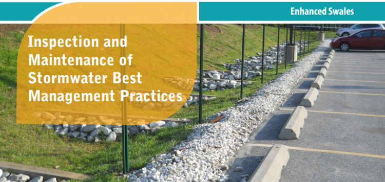
Enhanced swales are gently sloping vegetated open channels featuring a parabolic or trapezoidal cross-section and check dams, designed to convey and treat stormwater runoff (i.e., rainwater or snowmelt from roofs or pavements). The grading, Check dams and vegetation spreads out and slows down the flow of water, allowing suspended sediment and floatables (e.g., trash, natural debris, oil and grease) to settle out. A portion of the flowing water soaks into the soil and replenishes groundwater or is taken up by plant roots and evaporated back to the atmosphere. Runoff water is delivered to the practice through inlets such as curb cuts, spillways or other concrete structures, sheet flow from pavement edges, or pipes connected to catchbasins or roof downspouts. The planting bed and side slopes are typically covered with grasses or a mixture of flood tolerant, erosion resistant vegetation and stone. They do not feature filter media soil and sub-drains like bioretention or bioswales do. Water not ponded behind check dams or absorbed by the planting bed is conveyed to an adjacent drainage system (e.g., municipal storm sewer or other BMP) at the lowest downstream point by an outlet structure (e.g., ditch inlet catchbasin, culvert). Key components of this feature are described in further detail below.
Properly functioning enhanced swales reduce the quantity of pollutants and runoff being discharged to municipal storm sewers and receiving waters (i.e., rivers, lakes and wetlands). In addition to their SWM benefits, enhanced swales provide aesthetic value as attractive landscaped features.
Key components of Enhanced swales to pay close attention to are the:
Trash, debris and sediment builds up at these locations and can prevent water from flowing into or out of the practice.
Associated Practices[edit]
- Grass Swales: A parabolic or trapezoidal-sized bottom, swale that contains grassed sloping sides and a filter media bottom to both convey overland flow and provide water treatment, and are often subject to more frequent maintenance. They generally contain an outlet structure at the lowest point for water to be sent to another LID BMP or the storm system; sometimes referred to as a roadside ditch. Does not contain check dams.
- Swales: Swales are linear landscape features consisting of a drainage channel with gently sloping sides. Underground they may be filled with engineered soil and/or contain a water storage layer of coarse gravel material. Two variations on a basic swale are recommended as low impact development strategies, although using a combination of both designs may increase the benefit.
- Bioswales are sometimes referred to as 'dry swales', 'vegetated swales', or 'water quality swales'. This type of BMP is form of bioretention with a long, linear shape (surface area typically >2:1 length:width) and a slope which conveys water and generally contains various water tolerant vegetation
Inspection and Testing Framework[edit]


Component |
Indicators |
Construction Inspection |
Assumption Inspection |
Routine Operation Inspection |
Verification Inspection |
|---|---|---|---|---|---|
| Contributing Drainage Area | |||||
| CDA condition | x | x | x | x | |
| Inlet | |||||
| Inlet/Flow Spreader Structural Integrity | x | x | x | ||
| Inlet/Flow Spreader Structural Integrity | x | x | x | x | |
| Pretreatment sediment accumulation | x | x | x | ||
| Inlet erosion | x | x | |||
| Perimeter | |||||
| BMP dimensions | x | x | x | ||
| Side slope erosion | x | x | |||
| Surface ponding area | x | x | x | ||
| Filter Bed | |||||
| Standing water | x | x | x | ||
| Trash | x | x | |||
| Filter bed erosion | x | x | |||
| Filter bed sediment accumulation | x | x | x | ||
| Surface ponding depth | x | x | x | ||
| Filter bed surface sinking | x | x | x | ||
| Check dams | x | x | x | x | |
| Planting Area | |||||
| Vegetation cover | x | x | x | x | |
| Vegetation condition | x | x | |||
| Vegetation composition | x | x | x | ||
| Outlet | |||||
| Overflow outlet obstruction | x | x | x | x |
Component |
Indicators |
Construction Inspection |
Assumption Inspection |
Routine Operation Inspection |
Verification Inspection | |
|---|---|---|---|---|---|---|
| Testing Indicators | ||||||
| Soil characterization testing | x | x | (x) | |||
| Sediment accumulation testing | x | x | x | x | ||
| Surface infiltration rate testing | x | (x) | ||||
| Natural or simulated storm event testing | x | (x) | ||||
| Note: (x) denotes indicators to be used for Performance Verification inspections only (i.e., not for Maintenance Verification inspections) | ||||||

Construction Inspection Tasks[edit]
Construction inspections take place during several points in the construction sequence, specific to the type of LID BMP, but at a minimum should be done weekly and include the following:
- During site preparation, prior to BMP excavation and grading to ensure the CDA is stabilized or that adequate ESCs or flow diversion devices are in place and confirm that construction materials meet design specifications
- At completion of excavation and grading, prior to installation of pipes/sewers and backfilling to ensure depths, slopes and elevations are acceptable
- Prior to hand-off points in the construction sequence when the contractor is responsible for the work changes (i.e., hand-offs between the storm sewer servicing, paving, building and landscaping contractors
- After every large storm event (e.g., 15 mm rainfall depth or greater) to ensure Erosion Sediment Controls (ESCs) and pretreatment or flow diversion devices are functioning and adequately maintained. View the table below, which describes critical points during the construction sequence when inspections should be performed prior to proceeding further. You can also download and print the table here

Construction Sequence Step & Timing |
Inspection Item |
Observations* |
|---|---|---|
| Site Preparation - after site clearing and grading, prior to BMP excavation and grading | Natural heritage system and tree protection areas remain fenced off | |
| ESCs protecting BMP layout area are installed properly | ||
| CDA is stabilized or runoff is diverted around BMP layout area | ||
| BMP layout area has been cleared and is staked/delineated | ||
| Benchmark elevation(s) are established nearby | ||
| Construction materials have been confirmed to meet design specifications | ||
| BMP Excavation and Grading - prior to landscaping | Excavation location, footprint, depth and slopes are acceptable | |
| Excavated soil is stockpiled outside the CDA | ||
| Embankments/berms (elevations, slopes, compaction) are acceptable | ||
| Excavation bottom and sides roughened to reduce smearing and compaction | ||
| Landscaping – after final grading, prior to planting | Topsoil depth, degree of compaction and surface elevations at inlets and outlets are acceptable | |
| Maximum surface ponding depth is acceptable | ||
| Filter bed is free of ruts, local depressions and not overly compacted | ||
| Planting material meets approved planting plan specifications (plant types and quantities) | ||
| Note: for Observation Column: S = Satisfactory; U = Unsatisfactory; NA = Not Applicable* | ||
Routine Maintenance - Key Components and I&M Tasks[edit]
Regular inspections (twice annually, at a minimum) done as part of routine maintenance tasks over the operating phase of the BMP life cycle to determine if maintenance task frequencies are adequate and determine when rehabilitation or further investigations into BMP function are warranted.
Table below describes routine maintenance tasks for bioretention practices, organized by BMP component, along with recommended minimum frequencies. It also suggests higher frequencies for certain tasks that may be warranted for BMPs located in highly visible locations or those receiving flow from high traffic areas (vehicle or pedestrian). Tasks involving removal of trash, debris and sediment and weeding/trimming of vegetation for BMPs in such contexts may need to be done more frequently (i.e., higher standards may be warranted).
Individuals conducting vegetation maintenance and in particular, weeding (i.e., removal of undesirable vegetation), should be familiar with the species of plants specified in the planting plan and experienced in plant identification and methods of removing/controlling noxious weeds. Key resources on these topics are provided below at the links provided:
- Agriculture and Agri-food Canada’s Weed Info database
- Ontario Ministry of Agriculture, Food and Rural Affairs’ Ontario Weed Gallery
- Ontario Ministry of Agriculture, Food and Rural Affairs’ Noxious Weeds In Ontario list
- Ontario Invasive Plant Council’s Quick Reference Guide to Invasive Plant Species
- Oregon State University Stormwater Solutions, 2013, Field Guide: Maintaining Rain Gardens, Swales and Stormwater Planters, Corvallis, OR.
- Plants of Southern Ontario (book), 2014, by Richard Dickinson and France Royer, Lone Pine Publishing, 528 pgs.
- Weeds of North America (book), 2014, by Richard Dickinson and France Royer, University of Chicago Press, 656 pgs.
| Component | Description | Inspection & Maintenance Tasks | (Pass) Photo Example | (Fail) Photo Example |
|---|---|---|---|---|
| Contributing Drainage Area (CDA) |
Area(s) from which runoff directed to the BMP originates; includes both impervious and pervious areas. |
|
||
| Pretreatment |
Devices or features that retain trash, debris and sediment; help to extend the operating life cycle; examples are eavestrough screens, catch basin inserts and sumps, oil and grit separators, geotextile-lined inlets, gravel trenches, grass filter strips and forebays. |
|
 Forebay is free of sediment, trash and debris and recently maintained. The large stones in the feature are used to slow down and spread out inflowing water into the feature and they remain well arranged and in place. |
 An erosion gully occurring where bare soil is starting to become visible on the grass filter strip pretreatment feature at the inlet, thus indicating it is not effectively slowing and spreading out the inflow of stormwater to the BMP. |
| Inlets & Overflow Outlets |
Structures that deliver water to the BMP (e.g., Curb cuts, spillways, pavement edges, catch basins, pipes) or convey flow that exceeds the storage capacity of the BMP to another drainage system (i.e. other LID BMP, or storm sewer). |
|
||
| Perimeter |
Side slopes or structures that define the BMP footprint; may be covered by a mixture of vegetation, mulch and stone with slopes up to 3:1 (H:V), or concrete or masonry structures with vertical walls. |
|
||
| Filter Bed |
Linearly-oriented, gently sloping area (between 0.5 and 4% slope) where runoff is filtered and conveyed; parabolic or trapezoidal cross-section, lined with 20 to 30 cm of planting soil and covered with deep rooting perennial grasses or a mixture of vegetation and stone. |
|
||
| Vegetation |
Deep rooting perennial grasses or a mixture of wildflowers and shrubs, tolerant to both wet and dry conditions and salt; roots uptake water and return it to the atmosphere, provide habitat for organisms that break down trapped pollutants and help maintain soil structure and permeability |
|


- ↑ TRCA. 2016. Fact Sheet - Inspection and Maintenance of Stormwater Best Management Practices: Enhanced Swales. https://sustainabletechnologies.ca/app/uploads/2018/02/Enhanced-Swales-Fact-Sheet.pdf
- ↑ 2.0 2.1 Toronto and Region Conservation Authority (TRCA). 2019. Erosion and Sediment Control Guideline for Urban Construction. Toronto and Region Conservation Authority, Vaughan, Ontario. https://sustainabletechnologies.ca/app/uploads/2020/01/ESC-Guide-for-Urban-Construction_FINAL.pdf
- ↑ Connop S. and Nash, C. 2019. A Storm in a Bioswale: Breaking Down Barriers to Nature-Based Solutions. The Nature of Cities. 16 December 2019 Accessed: 4 July 2022. https://www.thenatureofcities.com/2019/12/16/a-storm-in-a-bioswale-breaking-down-barriers-to-nature-based-solutions/
- ↑ Vidacycle. 2020. Soil Monitoring Guide: Other Soil Tests. Accessed 4 July 2022. https://soils.vidacycle.com/soil-tests/