Sub-surface components

The construction guidance in this section applies to all sub-surface and ground-level LID practices: bioretention gardens, bioswales, rain gardens, exfiltration trenches, enhanced swales, permeable pavements, infiltration trenches, infiltration chambers, and soakaways. In general, this section describes construction and inspection processes for below ground installed materials and infrastructure that are part of the LID practices noted above.
Overview[edit]
This section gives guidance for project managers, engineers, and contractors on the installation of sub-surface components of LID practices.
Geotextiles[edit]
Geotextiles are filter fabrics that can be installed to separate dissimilar soils and prevent the migration of materials. Geotextiles are recommended for installation at the bottom and side limits of the LID feature and should be implemented at the discretion of the engineer.
Construction Steps:
- Roll out fabric on the flattened sub-grade surface.
- Provide a minimum overlap of 300 mm between adjacent lengths of geotextile. If the manufacturer specifies a greater overlap, follow the manufacturer’s specification.
- Secure fabric in place with stakes along the edge of the sub-grade surface and where lengths of fabric overlap.
- Provide 500 mm of excess at the ends of each length of fabric. Fold excess materiel on top of the infiltration medium/choker course once installed.
- Provide cuts for trees and shrubs where appropriate.
- Assess on-site conditions to ensure that the tensile, tear, and puncture strength ratings of the geotextile are suitable for expected structural loads (e.g. traffic). If not properly considered, geotextiles can be adversely impacted by loading from adjacent infrastructure uses.
Key Inspection Points:
- Geotextile is clean and free of damage.
- Geotextile delivered to the site matches the design specifications and is approved by the engineer prior to installation.
- Sufficient overlap is provided between lengths of fabric.
- Geotextiles have been applied as per the manufacturer’s guidelines.
- Structural considerations for geotextiles have been made when applied adjacent to infrastructure and the geotextile can handle expected structural loads.
- Class II geotextiles conform to OPSS 1860.
Mistakes to Avoid:
- Wrinkles in the fabric: Follow the manufacturer’s procedure for installation to ensure geotextiles lie smooth on sub-grade.
- Unnecessary application of geotextile: Mixing of media is negligible where structural loads are not expected, so geotextile does not need to be applied. Also, geotextiles should not be used where root growth is encouraged to penetrate different layers of media.
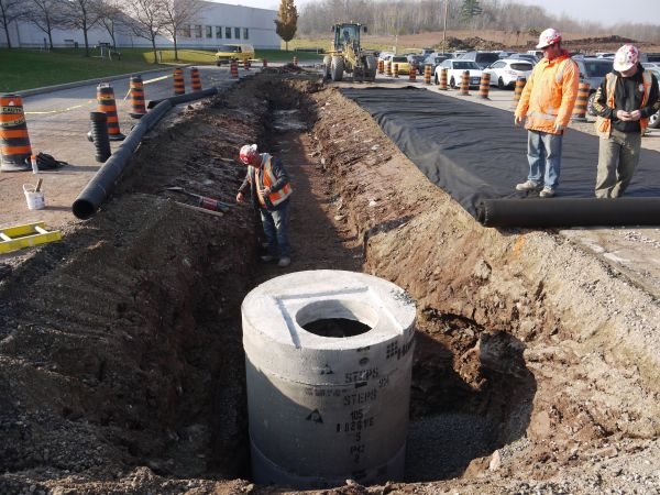
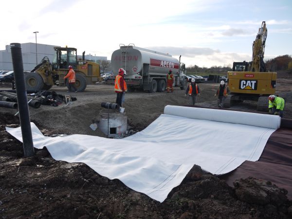
The shape of the LID feature required the geotextile to be rolled out prior to being laid on the subgrade surface. Photo taken during construction of IMAX Corporation Headquarters. (Photo Source: CVC, 2012)
Excess fabric is draped over the edges of the LID practice, and backfilling with granular is taking place. Photo taken during construction of IMAX Corporation Headquarters. (Photo Source: CVC, 2012)
Footprint with geotextile, granular, and underdrain. Photo taken during construction of IMAX Corporation Headquarters. (Photo Source: CVC, 2012)


Underdrains[edit]


Underdrains are perforated pipes that collect subsurface water and convey water out of an LID facility once it reaches capacity. Their design is determined by the drainage requirements of the feature.
Construction Steps:
- Install the underdrain to grade with a consistent slope of 0.5% to 1.0%.
- Connect overflow risers with single-elbowed ‘y’ connections or 45° elbows.
- Situate maintenance risers where siltation is expected in drain lines (such as at junctions or where grade and direction changes occur), in accordance with the design drawings.
- Mark the locations of risers.
- Use video inspections to confirm that the interior of the underdrain remains free of debris after construction.
Key Inspection Points:
- Size, type, and material of the underdrain conforms to the design specifications.
- Underdrain is perforated prior to arrival on-site.
- Drain material is resistant to UV radiation and any chemicals in the soil and groundwater.
- Clean-outs are positioned correctly and spaced appropriately for the size of the underdrain.
- Any manual perforations are approved by the design or field engineer.
- Pipe grade matches design specifications.
- Tie-in locations to municipal sewers meet municipal specifications.
Mistakes to Avoid:
- Incorrect overflow risers – ensure single-elbowed ‘y’ connections or 45° elbows are used for overflow risers instead of ‘T’ connections.
- Incorrect drain size – confirm underdrain has an internal diameter greater than or equal to 200 mm to reduce freezing and allow cleaning and camera inspections.
- Potential for clogging – Remove sock from underdrain prior to installation or geofabric wrap. A choker course is recommended, instead, as field change.
For more information on the design of underdrains, such as materials and connections, see the page on underdrains linked above.
Impermeable liners[edit]
Impermeable liners can be applied when LID features are not intended to infiltrate runoff into the underlying soil. They protect building foundations or other subsurface infrastructure. They also prevent infiltration through contaminated soils. Where building foundations next to the LID feature are not waterproofed, liners can be used to protect adjacent infrastructure.
Construction Steps:
- Compact 30 – 50 mm of sand over the soil onto which the membrane will be installed to protect against punctures. Alternatively, a geotextile can be used in the place of sand.
- Place lengths of liner on the bed of the facility as per the manufacturer’s specifications.
- Provide 150 mm of overlap between adjacent lengths of liner.
- Secure liner in-place and bond together the overlapping portions of liner as specified by the manufacturer.
- Seal a flange to the pipe and liner when pipes provide drainage from the practice.
- Compact sand or apply cushion fabric on top of the liner to protect against punctures.
Key Inspection Points:
- Liner matches design specifications.
- Liner installation procedures conform to manufacturer’s specifications.
- Minimum overlap between lengths of liner is achieved.
- Need for protection of building footprints and adjacent infrastructure confirmed through field verification of setbacks.
- Sand and/or geotextile are applied on both sides of the liner to protect against punctures.
- Lengths of liner are bonded together to ensure protection against groundwater penetration and contamination.
An impermeable liner was placed along one side of the LID facility to prevent infiltrated water from contacting the nearby watermain in the road right-of-way, which runs parallel to the feature. (Photo Source: CVC, 2020)
Impermeable Bentofix® liner being rolled out in LID practice area. (Photo Source: CVC, 2012)


Overflows[edit]
Overflows are features of inline facilities and convey larger storm events out of the LID feature.
Construction Steps:
- Connect the overflow drain to the underdrain.
- Fit a metal, domed grate to the overflow.
- Install overflow pit to grade at the location specified in the contract documents.
Key Inspection Points:
- Overflow drain matches design specifications.
- Overflow pit is positioned at the maximum water surface elevation of the practice, as per the contract documents.
- Sufficient freeboard is provided between the overflow and inlet such that the inlet is not inundated by design storm flows.
- Overflow grate matches design specifications.
- Overflow grates located in high-traffic areas are screwed on or equipped with locks.
Mistakes to Avoid:
- Backflows: Ensure that backflows are avoided by confirming that inlet and overflow elevations match design specifications with surveys.
- Incorrect sequencing: Install overflow drain prior to backfilling with granular material and engineered soil.
- Incorrect grate material: Avoid using plastic overflow grates due to breakages and UV degradation.
Overflow pipe installed to an underdrain T-connection. (Photo Source: CVC, 2010)
Overflow installed with a plastic cap. Note that the use of plastic grates is discouraged. (Photo Source: CVC, 2012)


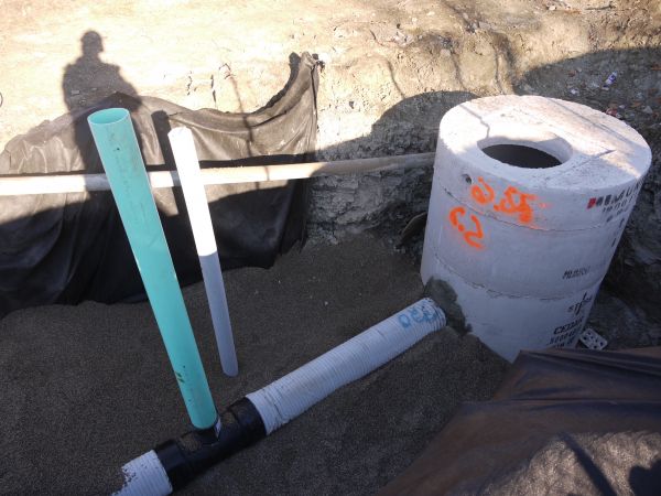
Monitoring wells[edit]

Monitoring wells allow for measurement of water levels in the sub-surface components of LID practices. They are important for sampling procedures and ensuring that the LID feature are performing as intended.
Construction Steps:
- Install a cap stand at the required elevation to anchor the monitoring well.
- Wrap the perforated pipe with a geotextile sock (to prevent migration of soil into the well).
- Anchor the perforated pipe to the bottom of the LID feature.
- Install a lockable cap to the top of the standpipe to protect against vandalism.
- Install monitoring equipment (e.g., a level logger) if required.
Key Inspection Points:
- Pipe is perforated, rigid, and matches design specifications.
- Well is installed according to contract documents.
- Geotextile sock is wrapped around the perforated portion of the well.
Mistakes to Avoid:
- Incorrect sequencing: Ensure that standpipe is installed prior to backfilling with granular material.
Storage reservoir[edit]
INSERT YOUTUBE LINK: https://www.youtube.com/watch?v=Ng_s2ErvPqk&t=58s
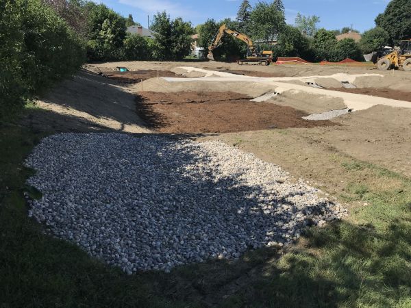
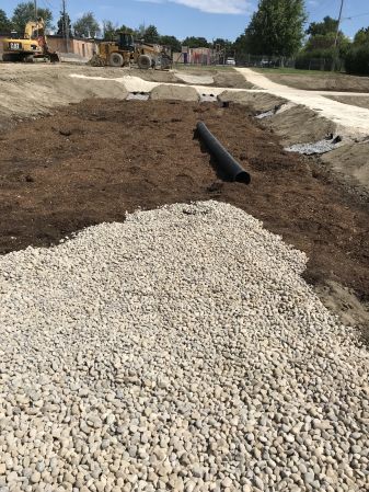
The storage reservoir layer holds and directs the stormwater into the underlying/native soils. The LID facilities, if applicable, should be filled with uniformly graded, washed stone (20 mm – 50 mm) that provides 30 to 40% void space.
Construction steps:
- Backfill material from outside of the LID facility to avoid compaction and sediment entering the facilities. Use a slinger truck if possible.
- Place the material to the elevation and thickness as per the design specifications.
Key Inspection Points:
- Material arrival to the site:
- Check chain of custody
- Verify it meets specifications as per design
- Verify no debris or fines within the aggregate (it’s a washed stone)
- Granular material should be 19 - 50 mm clear stone or as per design. See Aggregates for further details.
- Installed aggregate is at the correct elevation as per design.
Mistakes to Avoid:
- Accepting material that does not meet design requirements and specifications.
- Installing material with heavy equipment from the inside of the LID facility
- Installing frozen aggregate. Do not install frozen aggregate
- Leaving heavy equipment (excavator) for long periods of time within the LID facility.
For more guidance on materials specifications, refer to Aggregates, OPSS aggregates and (Ontario Provincial Standards, 2013) [1]
Permeable pavement sub-base and base course[edit]
Because permeable pavements may be required to support heavy loads (driveways, laneways, etc.), the sub-base and base course may require compaction to prevent heaving and shifting.
Sub-base reservoir[edit]
In permeable pavement systems, the sub-base is the layer of granular material that is laid on the sub-grade. The granular sub-base should be clear, crushed 50 mm stone. See the Permeable pavements: Specifications page for detailed sub-base material specifications. The construction steps, key inspection points, and mistakes to avoid for sub-base reservoir are the same as / similar to the guidance given in the storage reservoir section.
However, depending on the municipality and the design, compaction of the sub-base reservoir may be required. For example, the City of Toronto’s Construction Specification for Permeable Interlocking Concrete Pavers[2] details the following steps for sub-base installation.
Construction Steps:
- Place sub-base aggregate in 200 mm lifts (maximum)
- Compact each lift with a 9-ton vibratory roller, with two passes in vibratory mode and two passes in static mode, or until there is no visible movement of the aggregate.
- Use a plate compactor for smaller areas that the vibratory roller cannot reach.
Base course[edit]
In permeable pavement systems, the base course lies on top of the sub-base reservoir. See the Permeable pavements: Specifications page for base material specifications. The construction steps, key inspection points, and mistakes to avoid for the base course are the same as the guidance given in the storage reservoir section.
However, depending on the municipality and the design, compaction of the base course may be required. For example, the City of Toronto’s Construction Specification for Permeable Interlocking Concrete Pavers[3] details the following steps for base course installation.
Construction Steps:
- Place base course aggregate in 100 mm lifts (maximum)
- Compact each lift with a 9 ton vibratory roller, with two passes in vibratory mode and two passes in static mode, or until there is no visible movement of the aggregate.
- Use a plate compactor for smaller areas that the vibratory roller cannot reach.
References[edit]
Trench, Chamber, and Perforated Pipe Installation[edit]
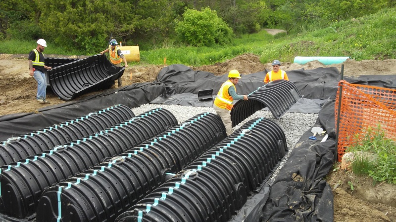
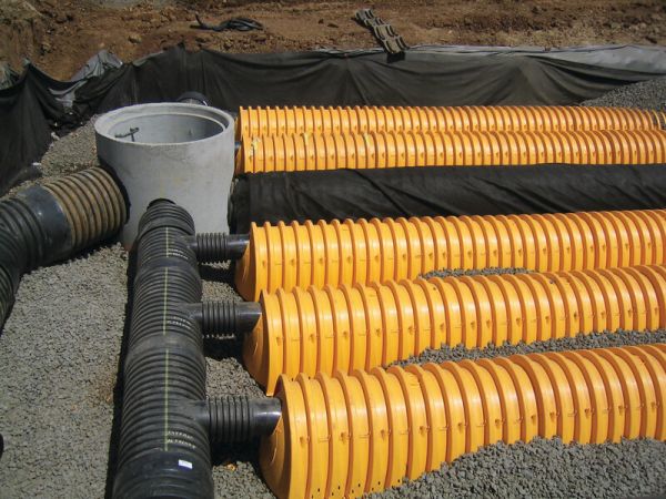
The guidance provided in this section is applicable for the construction of soakaway pits, infiltration chambers, infiltration trenches, and exfiltration pipes of varying size and shape, since the installation of each of these features is similar. The StormTech Installation Guide[4] is a key resource for understanding the construction of these features.

- Apply clear stone to the floor of the excavation to act as the base for chambers, pipes, and trenches.
- For infiltration chamber construction, install chamber feeder-pipes to the top of the base, connecting to the inlet control manhole, where applicable.
- Roll out scour fabric length-wise beside any feeder-pipes that have been installed, if specified in the design.
- If specified, lay out scour fabric where the base of the infiltration chamber, soakaway, or pipe is anticipated to be installed. No seams should be present where the fabric underlies chambers.
- Install chambers, trenches, or perforated pipes at the location and elevation specified in the contract documents. Where infiltration chambers need to be assembled from units, install each piece of the chamber row, as per the manufacturer’s instructions, until the entire length of the chamber is in place. The ends of the chamber may be installed just prior to perimeter stone being applied to the ends of the rows, if desired, to ensure ease of inspection.
- Connect any perforated pipe connections, underdrains, roof leaders, or observation wells at the appropriate elevations, per the design.
- With a stone conveyor or excavator, begin placing clear stone as specified in the design. For domed chambers, place stone along the centreline of the chamber rows. Doing so will distribute stone to either side of the chamber, anchoring each side in roughly equal proportion.
- Backfill the excavated area with clear stone to the depth specified in the contract documents. Ensure that the depth of stone does not differ by more than 300 mm between the sides of any given chamber row at any point during the backfilling process.
- Once backfilling is complete, level the perimeter stone with a small dozer. Only push material in the direction parallel to the rows.
- If specified by the design, roll geotextile parallel to rows over the top of stone. Provide sufficient overlap, as specified by the manufacturer.
Note: where many rows of infiltration chambers are being installed, it may be advisable to construct the chamber rows piece-wise as the application of perimeter stone progresses to provide space for excavators to apply the stone from on top of the stone base. See the adjacent photo for an example.
Key Inspection Points:
- Feeder-pipes protrude into the storm chambers at the appropriate length, per manufacturer’s specifications.
- Scour fabric does not overlap beneath the walls of open-bottom chambers.
- Minimum distance between adjacent chambers is provided.
- Minimum depth of stone below and stone above chamber is provided, per manufacturer specifications.
- Depth of chamber inverts are installed correctly, relative to the elevation of the inlet, such that the storage potential of chambers are maximized.
- Infiltration chambers are assembled as specified by the manufacturer.
- Perimeter stone extends to the excavation walls.
- LID practice is protected with applicable ESC to avoid contamination of infiltration area or materials.
Mistakes to Avoid:
- Equipment on the perimeter stone: Perimeter stone should be applied with a stone conveyor or excavator from the outside of the LID footprint or on the stone foundation.
- Uneven perimeter stone: Perimeter stone must be applied such that the depth of stone on one side of the chamber is not unacceptably higher than the other. Refer to design details.
- Incorrect inlet elevation: For applications where infiltration chambers overflow into a sewer, it is important that the top of chamber is positioned at an elevation below the lowest invert of the other sewer connections. Otherwise, only part of the chamber volume can be utilized.
- Damaged or missing ESC: Ensure that ESC protection is adequately inspected
- Putting system online prematurely: Do not allow the feature to receive stormwater when contributing drainage area is not stabilized and sediment and debris is present.
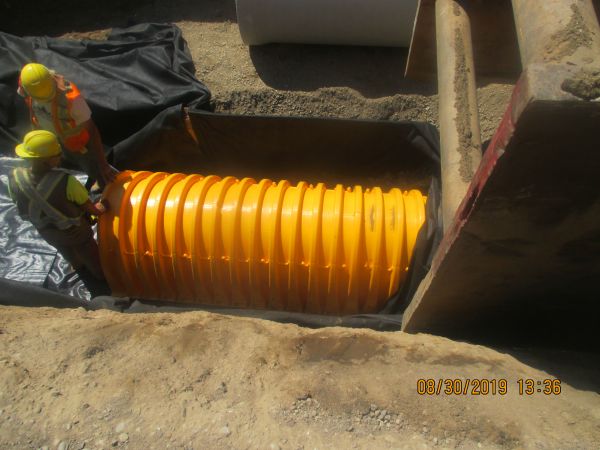
Chamber resting on top of scour fabric at Alton Main Street. (Photo Source: CVC, 2019)
Components of an infiltration chamber being overlapped. (Photo Source: CVC, n.d.)
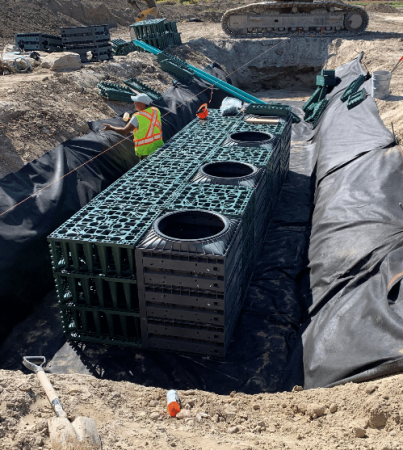
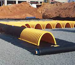
Example of "crate style" Infiltration chambers being installed in East Gwillimbury. (Photo Source: Make-Way Environmental Technologies Inc. Makeway Environmental Technologies Inc.)[6]
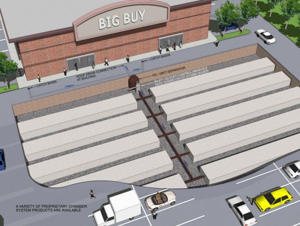
Example of an infiltration chamber system under a parking lot. (Photo Source: CVC, n.d.)
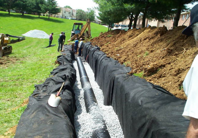
Infiltration trench equipped with a perforated pipe. (Photo Source: Cahill Associates Inc.)[7]
Manifold connecting to infiltration chamber rows. (Photo Source:Advanced Drainage Systems)[8]
Scour fabric rolled out below an infiltration chamber during assembly. (Photo Source: Advanced Drainage Systems)[9]
A storm chamber inlet protected from debride by an envirohood. It is essential that the top of the chamber is lower in elevation than any other outlets from the catchbasin. This is because the chamber’s capacity should be fully utilized before runoff is allowed to travel farther downstream. (Photo Source: CVC, 2022)


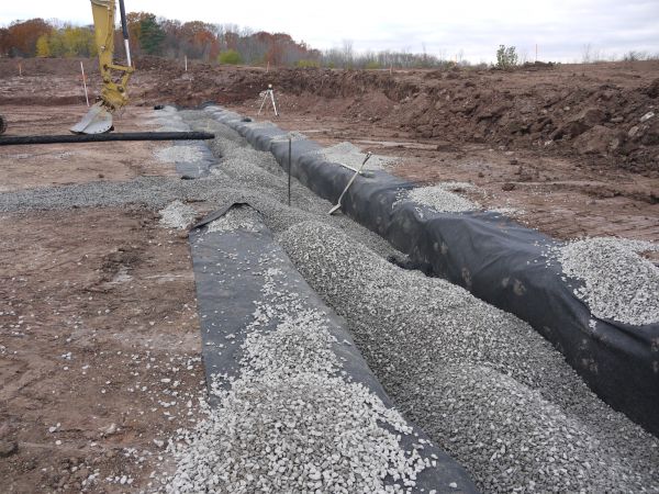
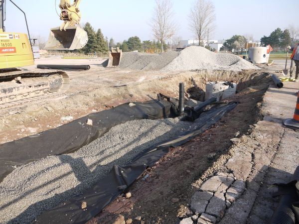
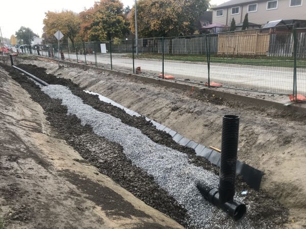
Stone choker layer[edit]
INSERT VIDEO: K:\Watershed Management\Integrated Water Management Implementation\Fletchers Creek SNAP\Haggert Ave Road Retrofit\3 - Photos\Construction Overview Presentation\Video--> HaggertAve_Final.MP4
In LID facilities, a choker layer of ≥ 100 mm depth is recommended to prevent migration of finer filter media into the underlying storage reservoir aggregate. Similar to the storage reservoir material, this aggregate layer should be a washed 5 – 10 mm stone free from fines and debris. Installation of aggregate choker layer should not be done when frozen.
Follow the construction guidance shown above in the section Storage reservoir
For more guidance on materials specifications, refer to Aggregates, OPSS aggregates and (Ontario Provincial Standards, 2013) [10]
Curbing[edit]

"'INSERT VIDEO FROM HAGGERT AVE: \\Hqcvcfs01\cvc2\Watershed Management\Integrated Water Management Implementation\Fletchers Creek SNAP\Haggert Ave Road Retrofit\3 - Photos\Construction Photos\Site Visit_20201120\Riverstone Construction Haggert Ave Inlet_F.mp4
It is very important to make sure that the contractor responsible for curb construction understands curb cut designs and elevations. This is often a new technique for contractors, and they may not understand the overall concept of water in the gutter line being directed behind the gutter.
Construction Steps:
- Place the right forms (rolled curve vs standard) in the inlet location.
- Pour concrete.
- Shape the inlet
- Add the river stone on top of the fresh concrete (if applicable)
- Provide sufficient curing time, according to (CSA, 2009)[11]

Key Inspection Points:
- Use of proper curb form by sub-contractor.
- Curb type aligns with design.
- Curb cut location, type and dimension aligns with design.
- Designated concrete wash out is in place and away from LID facility.
Mistakes to Avoid:
- Elevated curb cuts and reverse slopes (sloping from back of curb towards instead of depressing from gutter line towards the back).
- Wrong curb cut width size.
- Use of wrong curb form.
- Concrete wash out within or upstream of LID facility.
- Ensure curb granular base (granular A) does not spill over into LID infiltration area. If material spills over, remove as best as possible while still maintaining the 2:1 slope for curbing
- Lack of communication to concrete contractor or ready-mix driver explaining the function and importance of protecting the LID feature.
For more information on curb cuts, see these pages: Curb cuts, Curb cuts: Gallery and Bioretention: Streetscapes
Pretreatment and inlet[edit]
Pre-treatment structures are most cost effective when they slow down incoming flows, collect sediment for easy clean out, and slowly release water to the bioretention facility mitigating erosion. Pretreatment structures/strategies can include curb cuts, Aggregates, proprietary devices like filters or hydrodynamic separators, vegetation, concrete sumps, membrane filters, overland flow sumps, etc.
Construction Steps:
- Installation of pretreatment features will vary based upon type. Similarly, installation timeline will range with type and could occur at excavation and mass grading, curb work or at finishing grade. Given pre-treatment features are typically integrated with the LID inlet coordination amongst multiple sub-contractors is sometime needed. The following details steps for various pre-treatment types:
- Vegetation: Follow the guidance shown below in the section “Plant Material Verification and Installation”
- Curbing: Follow the guidance shown above in the section “Curbing”.
- Aggregate: Follow the guidance shown above in the section “Stone reservoir”.
Aggregate material (rock) installed as the inlet and pre-treatment device in the rain garden at Glendale P.S. in Brampton, ON. The runoff comes from a vegetated swale into the inlet, conveying it into the rain garden. (Photo Source: CVC, 2021)
Aggregate material (rock) installed as the inlet and pre-treatment device in the rain garden at Glendale P.S. in Brampton, ON. The runoff comes from a vegetated swale into the inlet, conveying it into the rain garden. (Photo Source: CVC, 2021)
Aggregate material (rock) installed as the inlet and pre-treatment device in the rain garden at Glendale P.S. in Brampton, ON. The runoff comes from a vegetated swale into the inlet, conveying it into the rain garden. (Photo Source: CVC, 2021)


Proprietary pre-treatment device[edit]
- Excavate and prepare base for proprietary pre-treatment device according to design.
- Install proprietary pre-treatment device according manufacturer directions.
- Manufacturer representative may need to confirm proper installation and functioning through approved testing and inspection.
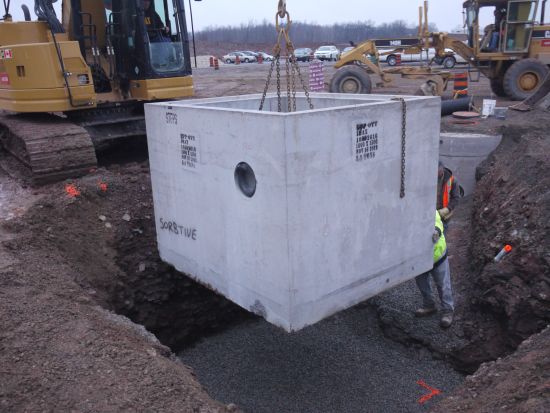
Installation of Jellyfish filter and sorbtive media vault at the IMAX bioswale project in Mississauga, ON. (Photo Source: CVC, 2012)
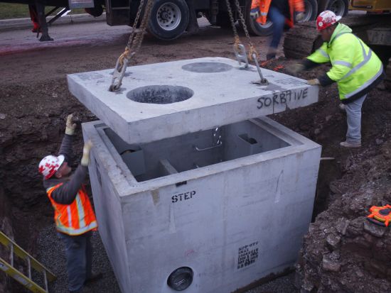
Installation of Jellyfish filter and sorbtive media vault at the IMAX bioswale project in Mississauga, ON. (Photo Source: CVC, 2012)
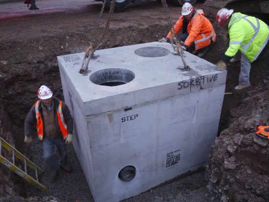
Installation of Jellyfish filter and sorbtive media vault at the IMAX bioswale project in Mississauga, ON. (Photo Source: CVC, 2012)


Key Inspection Points:
- Verify that the correct pre-treatment device (jellyfish filter, vegetation, curbing, etc.) is being installed.
- Verify that all components of the pre-treatment device are installed
- Verify correct size and location of pre-treatment device.
- Verify correct elevation, slope, and footing according to design
- Is it tied into the curb, downspout, or other inlet? Or could happen before the curbing?
- Wet weather performance check:
- Does it work?
- Is water entering the LID facility properly?
- Is sediment and debris accumulating?
- Is it dissipating erosive forces?
Mistakes to Avoid:
- Pre-treatment component parts are missing
- Grading/elevation errors that deviates from design
- Incorrect pipe inverts causing short circuiting
- Insufficient grade drop or slope into pre-treatment to ensure positive flow of water
- Improper grading from pre-treatment to LID feature inhibiting positive flow
- Insufficient sump depth to account for sediment and debris accumulation
- Using wrong concrete forms if concrete curbs are part of pre-treatment.
For more information about pre-treatment strategies and their design, visit these page(s): Pretreatment and Pretreatment features.
References[edit]
- ↑ Ontario Provincial Standards. 2013. OPSS.PROV.10101 Aggregates - Base, Subbase Select Subgrade, and Backfill Material. https://www.roadauthority.com/Standards/?id=a28fdfaf-3bf8-4679-81ca-4e44b2263cf8
- ↑ City of Toronto. 2021. TS 861 Construction Specifications for Permeable Interlocking Concrete Pavers. https://www.toronto.ca/wp-content/uploads/2021/08/952c-ecs-specs-gi-specs-TS861Sep2021.pdf
- ↑ City of Toronto. 2021. TS 861 Construction Specifications for Permeable Interlocking Concrete Pavers. https://www.toronto.ca/wp-content/uploads/2021/08/952c-ecs-specs-gi-specs-TS861Sep2021.pdf
- ↑ Advanced Drainage Systems. 2022. StormTech® Installation Guide MC-7200 Chamber. https://assets.ads-pipe.com/m/446afe5e1aafda1a/original/MC-7200-StormTech-Chamber-Installation-Guide.pdf
- ↑ Municipal Sewer & Water. 2022. Photo. Accessed in July 8 2022:https://www.mswmag.com/g/product-focus/2015/08/stormwater_management_advanced_drainage_systems_stormtech_mc_4500
- ↑ Makeway Environmental Technologies Inc. 2022. Stormwater Management. Photo. Accessed September 30, 2022: https://www.makeway.ca/products/stormwater-management-systems/
- ↑ Cahill Associates Inc. 2013. Infiltration Trench. Photo. Accessed September 30, 2022: http://www.malvern.org/wp-content/uploads/2013/03/Infiltrench.pdf
- ↑ Advanced Drainage Systems. 2022. StormTech Isolator Row PLUS. Photo. Accessed September 30, 2022: https://www.adspipe.com/water-management-solutions/detention-infiltration/isolator-row
- ↑ Advanced Drainage Systems. 2022. SC-160LP, SC-310, SC-740 & DC-780 Design Manual. Photo. Accessed September 30, 2022: https://assets.ads-pipe.com/m/770e887b972da86f/original/SC-160LP-SC-310-SC-740-DC-780-StormTech-Design-Manual.pdf
- ↑ Ontario Provincial Standards. 2013. OPSS.PROV.10101 Aggregates - Base, Subbase Select Subgrade, and Backfill Material. https://www.roadauthority.com/Standards/?id=a28fdfaf-3bf8-4679-81ca-4e44b2263cf8
- ↑ CSA. 2009. A23.1-09/A23.2-09 (R2014). Concrete materials and methods of concrete construction/Test methods and standard practices for concrete. standard A23.1-09. https://www.csagroup.org/store/product/2420232/#:~:text=and%20specialty%20concretes.-,A23.,A%20sister%20standard%20%E2%80%93%20CSA%20A23